
Compensation method for pulse counting accuracy of double-stage flowmeter verification device

A technology of pulse counting and precision compensation, which is applied in measuring devices, test/calibration devices, liquid/fluid solid measurement, etc., can solve the problems of adding hardware equipment, hardware devices with poorly considered interference, and phase deviation in phase coincidence detection, etc., to achieve The effect of high pulse counting accuracy, elimination of low-frequency interference, and improvement of compensation efficiency

Active Publication Date: 2017-06-30
GUANGZHOU INST OF ENERGY TESTING
View PDF12 Cites 0 Cited by
  • Summary
  • Abstract
  • Description
  • Claims
  • Application Information

AI Technical Summary

Problems solved by technology

[0004] (1) The common phase coincidence detection circuit is the D flip-flop method. However, if there is phase noise or trigger error in any one of the measurement comparison signals or two measurement comparison signals at the same time, it will have a relatively large impact on the phase coincidence detection output pulse, making There is a phase deviation in the final phase coincidence detection
However, the application of this patent in the double-stage flowmeter verification device requires additional hardware equipment, is not suitable for verifying flowmeters with small instrument coefficients, and has problems such as frequency multiplication of interference pulses and deterioration of measurement results.
[0009] Other non-integral cycle interception signal counting accuracy improvement methods, such as CN1193503 C, CN102565673 B, CN102931975 A, etc., also have problems such as insufficient consideration of interference or the need for additional complex hardware devices

Method used


Image

  • Compensation method for pulse counting accuracy of double-stage flowmeter verification device
  • Compensation method for pulse counting accuracy of double-stage flowmeter verification device
  • Compensation method for pulse counting accuracy of double-stage flowmeter verification device

Examples


Embodiment Construction

[0022] In order to make the object, technical solution and advantages of the present invention clearer, the present invention will be further described in detail below in conjunction with the embodiments and accompanying drawings.

[0023] Below in conjunction with embodiment and attached figure 1 The present invention is described in further detail:

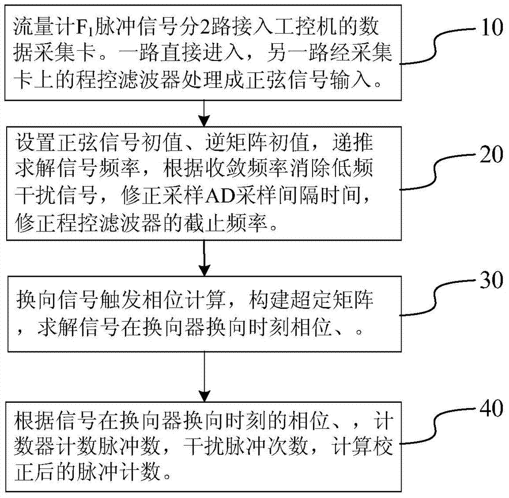
[0024] A method for compensating the pulse counting accuracy of a double-stage flowmeter verification device. The specific steps include:

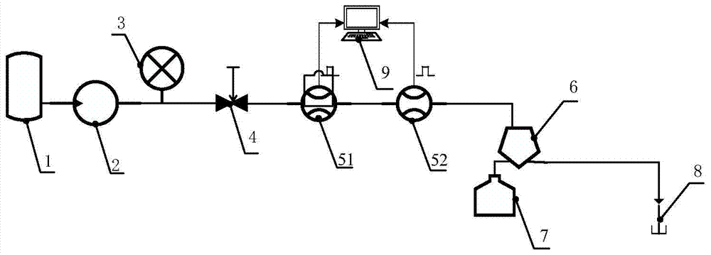
[0025] Step 10, flow meter F 1 The pulse signal is connected to the data acquisition card of the industrial computer in two ways; one way is directly used for counting, and the other way is processed by the program-controlled filter on the acquisition card into a sinusoidal signal input for pulse counting accuracy compensation;

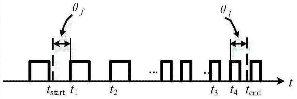
[0026] Other physical parameters that the method needs to collect include: commutator commutation signal start and end time t start , t end , AD value ADC of pu...


PUM


Abstract

The invention discloses a pulse counting precision compensation method for dual-bit flowmeter calibrating device, the method comprises the steps as follows: connecting the pulse signal of the flowmeter F1 to the data collecting card of industrial personal computer (IPC) in two paths; one path is direct while the other path is processed into the sinusoidal signal for input by the programmable filter on the collecting card; setting the sinusoidal signal initial value x(O), inverse matrix initial value P(O), obtaining the signal frequency omega, eliminating low frequency interference signal according to the convergence frequency, correcting the AD sampling interval time Ts; calculating reversing signal triggering phase for building over-determination matrix, obtaining the phase of the signal at reversing time for reverser, according to the phase of the signal at reversing time for reverser, counting the pulse number Ni by the counter, interference pulse number Nd and calculating the correction pulse number N.

Description

technical field [0001] The invention relates to the technical field of flow measurement equipment, in particular to a pulse counting precision compensation method for a double-stage flowmeter verification device. Background technique [0002] With the development of modern industry, the demand for flowmeters continues to increase, especially the pulse output flowmeter (in the case of a stable flow field, the instantaneous flow rate of the pulse output flowmeter is proportional to the pulse frequency) has been unprecedentedly applied, which is of great significance for its rapid and accurate verification. major. Universal verification device, the industrial computer drives the commutator according to the phase-locked signal of the pulse signal of the flowmeter, and can intercept the pulse signal of the flowmeter for the entire period. However, in a dual-stage installation, the measurement accuracy requirements for the pulse count of the other flowmeter cannot be guaranteed. ...

Claims


Application Information

Patent Timeline
Patent Type & Authority Patents(China)
IPC IPC(8): G01F25/00
Inventor 杨茹潘云飞万勇刘雅杰张达远
Owner GUANGZHOU INST OF ENERGY TESTING
Learn More