Over-temperature protection method and device

A technology of over-temperature protection and real-time temperature, applied in emergency protection circuit devices, emergency protection devices with automatic disconnection, circuit devices, etc., can solve the problems of IGBT module over-temperature burnout, temperature sensor can not reflect the temperature of the wafer in real time, etc. , to avoid overheating and burning

Active Publication Date: 2015-01-07
深蓝汽车科技有限公司
View PDF5 Cites 37 Cited by
  • Summary
  • Abstract
  • Description
  • Claims
  • Application Information

AI Technical Summary

Problems solved by technology

[0004] In view of this, the object of the present invention is to provide an over-temperature protection method and device to overcome the problem in the prior art that the temperature sensor cannot reflect the temperature at the wafer in real time, which easily leads to the over-temperature burning of the IGBT module

Method used


Image

  • Over-temperature protection method and device
  • Over-temperature protection method and device
  • Over-temperature protection method and device

Examples


Embodiment 1

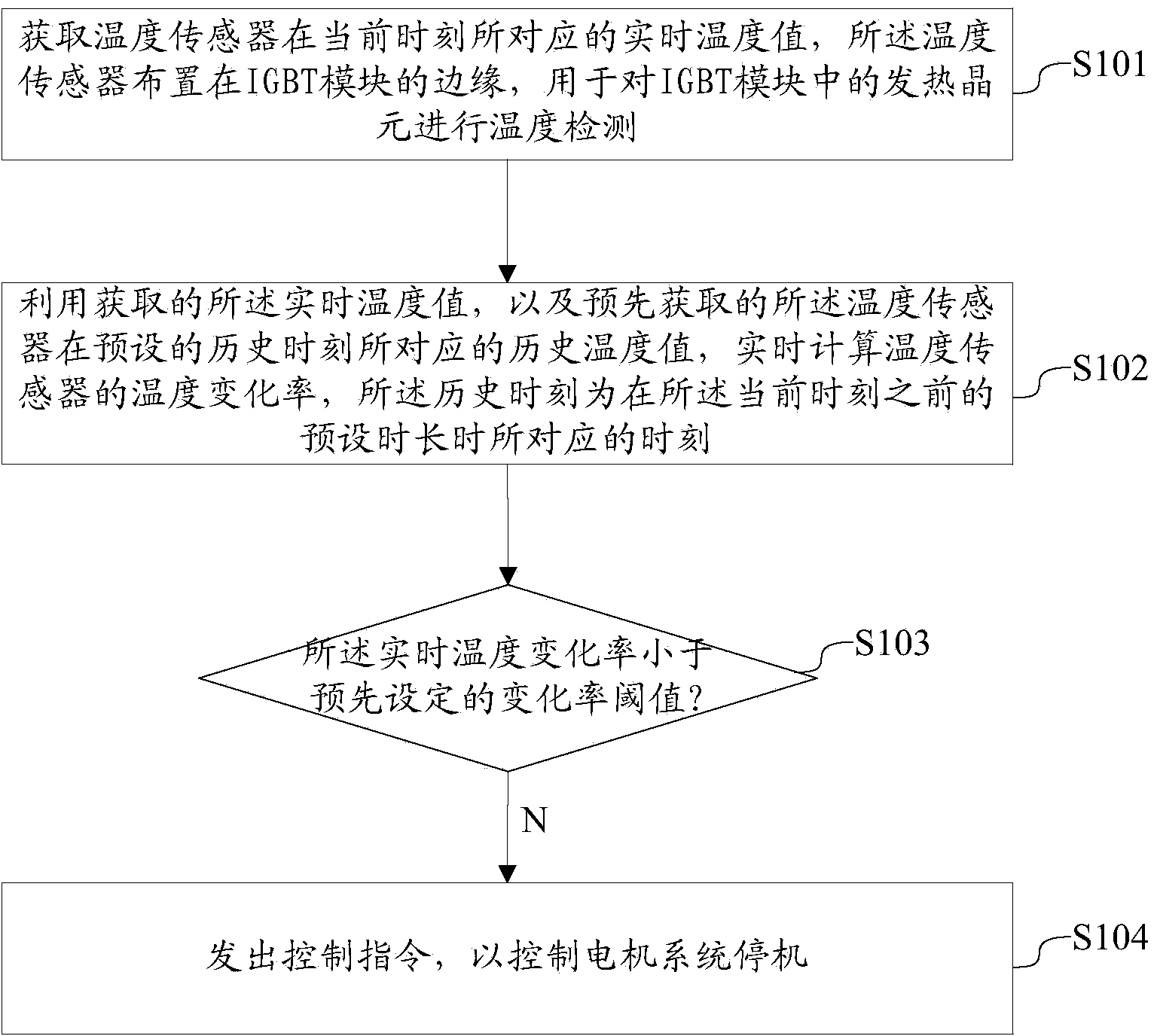
[0035] This embodiment 1 discloses an over-temperature protection method, which is used for over-temperature protection of the IGBT module when the cooling system is abnormal, refer to figure 1 , the method may include the following steps:

[0036] S101: Obtain a real-time temperature value corresponding to a temperature sensor at the current moment, the temperature sensor is arranged on the edge of the IGBT module, and is used to detect the temperature of the heating element in the IGBT module.

[0037] The applicant has found through research that when the temperature of the IGBT crystal element rises rapidly due to an abnormal cooling system, although the real-time temperature of the temperature sensor is much lower than the crystal element temperature of the IGBT at the same time, the temperature of the sensor will change with the crystal element temperature. The synchronous rapid rise is much greater than the temperature change rate of the sensor when the cooling system i...

Embodiment 2

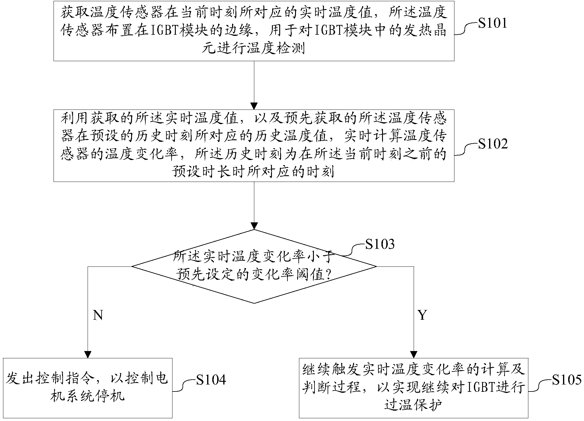
[0060] In the second embodiment, refer to image 3 , the over-temperature protection method also includes the following steps:

[0061] S105: If the judgment result is yes, continue to trigger the calculation and judgment process of the real-time temperature change rate, so as to continue to perform over-temperature protection on the IGBT.

[0062] That is, in this embodiment, if k正 +k 异 ) / 2, it means that the temperature change of the temperature sensor and the heating element in the IGBT is relatively stable, so the heat dissipation of the IGBT is normal, and the cooling system has no abnormality. In this case, the motor is not triggered to stop, and the temperature change of the temperature sensor continues The rate is detected to realize the real-time over-temperature protection of the IGBT module.

Embodiment 3

[0064] Embodiment 3 discloses an over-temperature protection device, which corresponds to the over-temperature protection method disclosed in Embodiment 1 and Example 2.

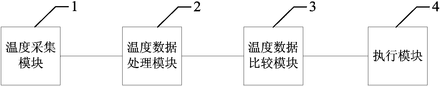
[0065] First, corresponding to Embodiment 1, refer to Figure 4 , the device includes an acquisition module 100 , a calculation module 200 , a judgment module 300 and a first protection module 400 .

[0066] The acquisition module 100 is used to acquire the real-time temperature value corresponding to the temperature sensor at the current moment, the temperature sensor is arranged on the edge of the IGBT module, and is used to detect the temperature of the heating element in the IGBT module.

[0067] The calculation module 200 is configured to calculate the real-time temperature change rate of the temperature sensor by using the acquired real-time temperature value and the pre-acquired historical temperature value corresponding to the temperature sensor at a preset historical moment, and the historical momen...


PUM


Abstract

The invention discloses an over-temperature protection method and device. Over-temperature protection is carried out on an IGBT without taking the real-time temperature of a temperature sensor as the reference but the real-time temperature change rate of the temperature sensor, particularly, when the real-time temperature change rate of the temperature sensor reaches a preset value, unusual conditions are known, a motor system is controlled to stop in time, and the purpose of over-temperature protection is realized. According to the research, when the temperature of an IGBT wafer rapidly rises due to the abnormal condition of a cooling system and the like, even though the real-time temperature of the temperature sensor is far smaller than the temperature of the IGBT wafer at the same time, the temperature of the sensor will synchronously and rapidly rise along with the changes of the temperature of the wafer and is largely larger than the normal temperature change rate of the sensor of the cooling system. Compared with the prior art, the real-time temperature change rate of the temperature sensor is used as the reference parameter and can more accurately reflect the happening abnormal conditions, and the phenomenon of over-temperature burning of the IGBT module is effectively avoided.

Description

technical field [0001] The invention belongs to the technical field of automotive electronic control, and in particular relates to an over-temperature protection method and device. Background technique [0002] The more energy-saving and environmentally friendly new energy vehicles led by electric vehicles have gradually become the key development targets in the automotive field. Electric vehicles are powered by rechargeable power batteries and driven by motors. [0003] At present, IGBT (Insulated Gate Bipolar Transistor, insulated gate bipolar transistor) is generally used as the drive module of the motor. Due to the high power of the electric vehicle motor, the IGBT needs to handle a large current and generate more heat. For this reason, cooling is generally used. The system dissipates heat from the IGBT, and uses a temperature sensor to detect the temperature of the heating element in the IGBT in real time. When the temperature of the sensor reaches a certain value, the ...

Claims


Application Information

Patent Timeline
Patent Type & Authority Applications(China)
IPC IPC(8): H02H5/04
Inventor 孙韬薛山
Owner 深蓝汽车科技有限公司
Why Eureka
Try Eureka