Stator and rotor for an electric machine

A stator and rotor technology, applied in the field of stator and rotor, adjustable pole motors, can solve the problems of small size and low speed of claw pole motors, and achieve the effects of easy assembly, bending prevention and cost reduction

Inactive Publication Date: 2015-01-07
HOGANAS AB
View PDF7 Cites 27 Cited by
  • Summary
  • Abstract
  • Description
  • Claims
  • Application Information

AI Technical Summary

Problems solved by technology

Currently, claw pole motors are limited to small size and / or low speed if the stator is constructed entirely of steel like common motors used as automotive alternators

Method used


Image

  • Stator and rotor for an electric machine
  • Stator and rotor for an electric machine
  • Stator and rotor for an electric machine

Examples


Embodiment Construction

[0071] In the following description, reference is made to the accompanying drawings which illustrate, by way of illustration, how the invention may be practiced. Like reference numerals designate like or corresponding components, elements and features throughout the drawings.

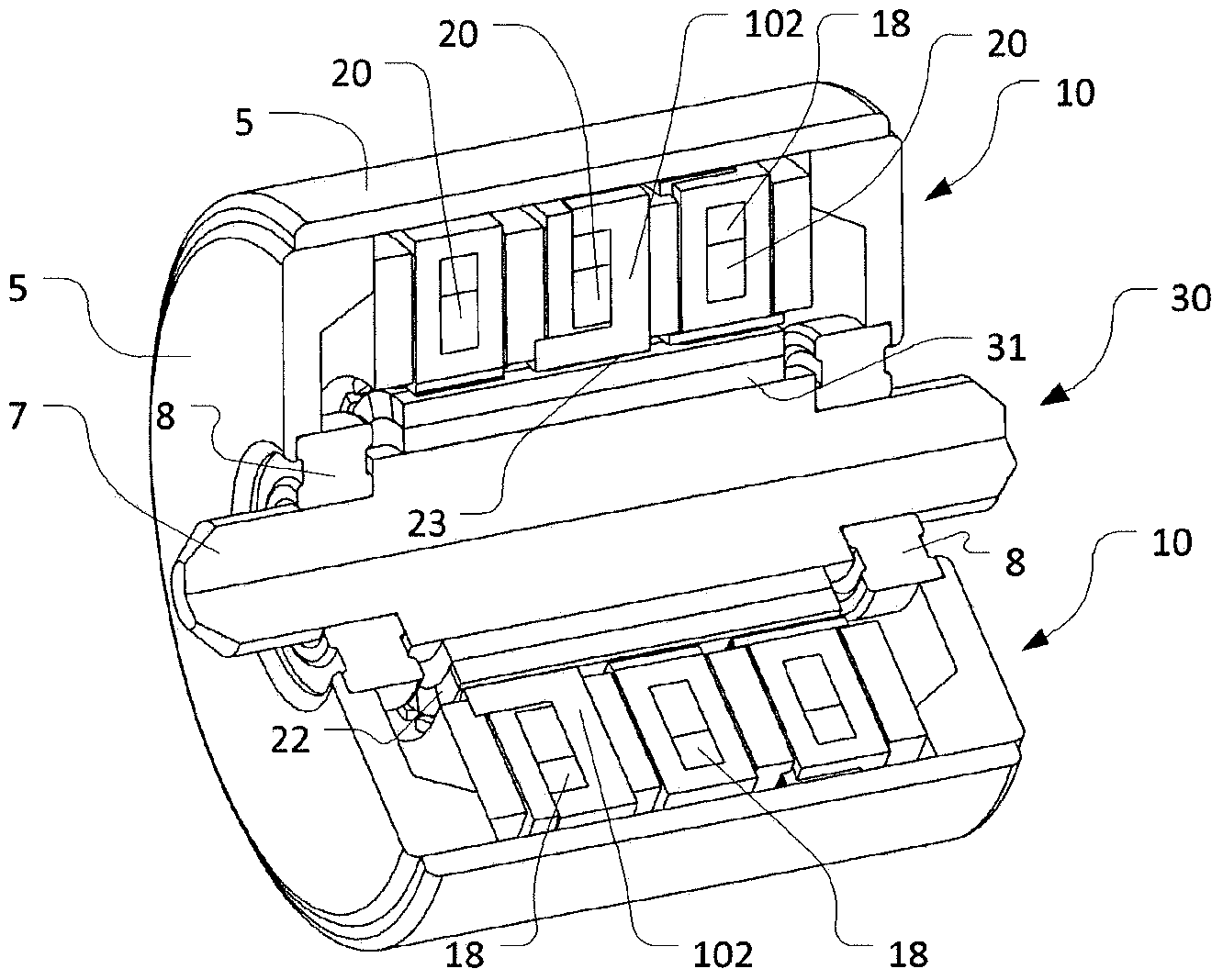
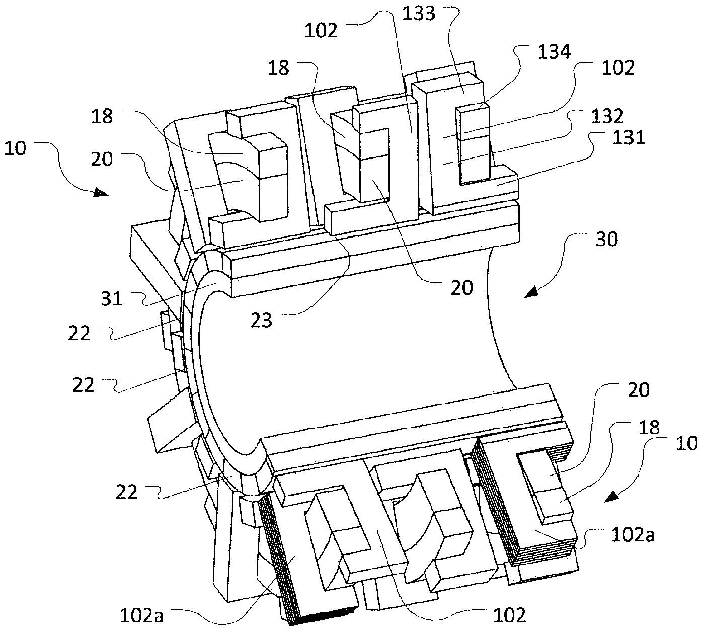
[0072] Figure 1a and 1b An example of a three-phase inner rotor modulated pole motor is illustrated. Particularly, Figure 1a shows a perspective view of the motor with part of the motor cut away, and Figure 1b A corresponding view showing the magnetically active components of the motor.

[0073] The electric machine comprises a housing 5, a stator 10 and a rotor 30 arranged inside the housing such that a rotor shaft 7 protrudes axially from the housing 5, the rotor being supported by bearings 8 to allow the rotor to rotate relative to the housing . The stator 10 and the rotor 30 surround a common geometric axis defined by the rotor shaft 7 . The rotor and stator define an effective air gap 23 be...


PUM


Abstract

A stator for an electric machine, the stator comprising a stator core and a winding. The stator core comprises an annular stator core back component providing a magnetic flux path in a circumferential direction and in an axial direction of the annular stator core back component; and a plurality of stator pole components each comprising a mounting part mounted to the stator core back component, an interface part defining an interface surface facing an active air gap between the stator and a rotor of the electrical machine;and a radially oriented tooth part extending radially from the annular stator core component and connecting the interface part with the mounting part.

Description

technical field [0001] The present invention relates generally to electric machines, and more particularly to modulated pole electric machines. More specifically, the invention relates to stators and rotors for such electrical machines. Background technique [0002] Over the years, motor designs such as modulated pole machines, such as claw pole machines, Lundell machines and transverse flux machines (TFM) have attracted increasing attention. Motors using the principles of these motors are disclosed in US Patent US 437501 as early as 1890 and Alexandersson and Fessenden around 1910. One reason for the increased interest is that the design achieves very high torque outputs relative to motors such as induction motors, switched reluctance motors, and even permanent magnet brushless motors. Furthermore, such motors are advantageous in that the coils are generally easy to manufacture. However, one of the disadvantages of this design is that they are generally expensive to manu...

Claims


Application Information

Patent Timeline
Patent Type & Authority Applications(China)
IPC IPC(8): H02K1/14H02K21/14H02K21/16
CPCH02K21/145H02K1/145Y10T29/49009H02K1/141H02K1/27H02K15/022
Inventor G·诺德J·华盛顿
Owner HOGANAS AB
Why Eureka
Try Eureka