
Positioning claw for inner hole positioning clamp

A technology of positioning fixture and positioning claw, applied in positioning device, clamping, clamping device and other directions, can solve the problems of increasing manufacturing cost, small application range, poor locking and positioning effect, etc., and achieves good positioning and locking effect, The effect of wide application and high precision machining

Inactive Publication Date: 2015-01-14
WUHU HUAYI VALVE MFG
View PDF7 Cites 0 Cited by
  • Summary
  • Abstract
  • Description
  • Claims
  • Application Information

AI Technical Summary

Problems solved by technology

In the existing market, various positioning fixtures for the inner hole of the pump generally adopt the method of positioning the inner hole by the positioning shaft, but the various positioning shafts in the prior art generally only play the role of positioning the inner hole, but do not play the role of locking the inner hole. The effect of this method makes it generally necessary to install a locking device for auxiliary positioning shaft positioning in the existing various pump body hole fixtures. This method increases the manufacturing cost, and has cumbersome operation, complex structure, small application range and locking and positioning effect. Inferior disadvantages, and the most important thing about a fixture is the positioning device, the core component of the positioning device is the positioning claw, so how to design a reasonable positioning claw is the key factor to solve the above problems

Method used


Image

  • Positioning claw for inner hole positioning clamp
  • Positioning claw for inner hole positioning clamp

Examples


Embodiment Construction

[0012] In order to make the technical means, creative features, goals and effects achieved by the present invention easy to understand, the present invention will be further described below in conjunction with specific illustrations. It should be noted that, in the case of no conflict, the embodiments in the present application and the features in the embodiments can be combined with each other.

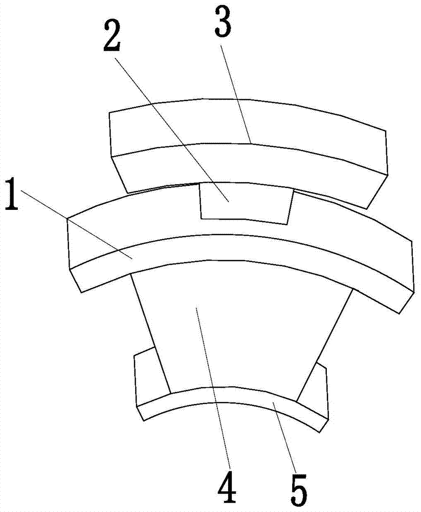
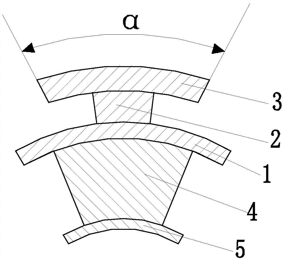
[0013] Such as figure 1 and figure 2 As shown, a positioning claw for an inner hole positioning fixture includes an upper positioning ring 1, an upper jacking block 2, an extrusion ring 3, a lower jacking block 4 and a lower positioning ring 5, and the upper jacking block 2 is welded on the upper The upper end of the positioning ring 1, the upper top block 2 plays the role of supporting the extrusion ring 3; the extrusion ring 3 is fixedly connected to the upper end of the upper top block 2, and the extrusion ring 3 squeezes the hole wall in the pump body, extruding The angle of t...


PUM


Abstract

The invention relates to a positioning claw for an inner hole positioning clamp. The positioning claw comprises an upper positioning ring, an upper ejection block, an extrusion ring, a lower ejection block and a lower positioning ring, wherein the upper ejection block is welded at the upper end of the upper positioning ring and is used for supporting the extrusion ring; the extrusion ring is fixedly connected to the upper end of the upper ejection block; the extrusion ring is used for extruding the wall of an inner hole of a pump body; the angle of the extrusion ring relative to the axis is alpha; the lower ejection block is welded at the lower end of the upper positioning ring and is used for supporting the upper positioning ring; the lower positioning ring is fixedly connected to the lower end of the lower ejection block and is used for limiting the upper ejection block to move upwards, so that the movement range of the positioning claw can be within a control range of operation personnel. The positioning claw can assist an inner hole clamp of the pump body in realizing the positioning and locking effects of the inner hole of the pump body, so that the inner hole of the pump body can be stably machined with high precision; the positioning claw has the advantages of easiness and convenience in operation, wide application range, good positioning and locking effects and the like.

Description

technical field [0001] The invention relates to a positioning fixture for auto parts, in particular to a positioning claw for an inner hole positioning fixture. Background technique [0002] The various pump accessories on the car include fuel pumps, oil pumps, brake master cylinders, brake sub-cylinders, water pumps, clutch master cylinders and clutch sub-cylinders, etc., and various pump accessories are composed of many parts. Among the parts, the pump body is the part with the longest processing time and the most complicated process. During the processing of the hole in the pump body, the positioning of the hole in the pump body needs to be realized by positioning fixtures, which can be realized through various positioning fixtures for auxiliary pump body processing. Smooth and high-precision machining of the pump body hole, therefore, the positioning fixture for auxiliary pump body processing plays a vital role in the process of pump body hole processing. In the existin...

Claims


Application Information

Patent Timeline
Patent Type & Authority Applications(China)
IPC IPC(8): B23Q3/18
CPCB23Q3/18B23Q2703/10
Inventor 沈德华汪阳
Owner WUHU HUAYI VALVE MFG
Learn More