A positioning device for an inner hole positioning fixture

A technology for positioning fixtures and positioning devices, which is applied in the direction of positioning devices, clamping, and manufacturing tools, and can solve the problems of lack of inner hole locking, poor locking and positioning effects, and increased manufacturing costs, and achieve positioning and locking Good effect, low manufacturing cost and easy operation

Active Publication Date: 2017-01-25
ZHANGJIAGANG DONGDA IND TECH RES INST
View PDF5 Cites 0 Cited by
  • Summary
  • Abstract
  • Description
  • Claims
  • Application Information

AI Technical Summary

Problems solved by technology

In the existing market, various positioning fixtures for the inner hole of the pump generally adopt the method of positioning the inner hole by the positioning shaft, but the various positioning shafts in the prior art generally only play the role of positioning the inner hole, but do not play the role of locking the inner hole. The effect of this method makes it generally necessary to install a locking device for auxiliary positioning shaft positioning in the existing various pump body hole fixtures. This method increases the manufacturing cost, and has cumbersome operation, complex structure, small application range and locking and positioning effect. Inferior disadvantages; and the most important thing about a fixture is the positioning device, so how to design a reasonable positioning device is the key factor to solve the above problems

Method used


Image

  • A positioning device for an inner hole positioning fixture
  • A positioning device for an inner hole positioning fixture
  • A positioning device for an inner hole positioning fixture

Examples


Embodiment Construction

[0013] In order to make it easy to understand the technical means, creative features, objectives and effects achieved by the present invention, the present invention will be further explained below in conjunction with specific drawings. It should be noted that the embodiments in the application and the features in the embodiments can be combined with each other if there is no conflict.

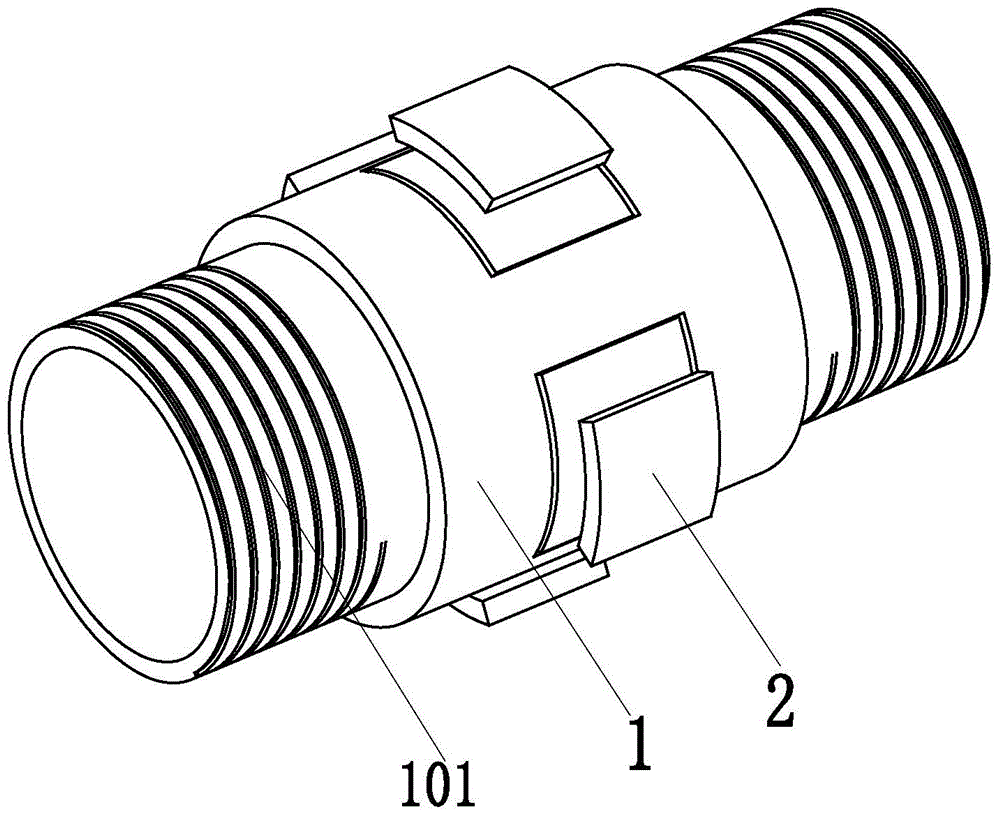
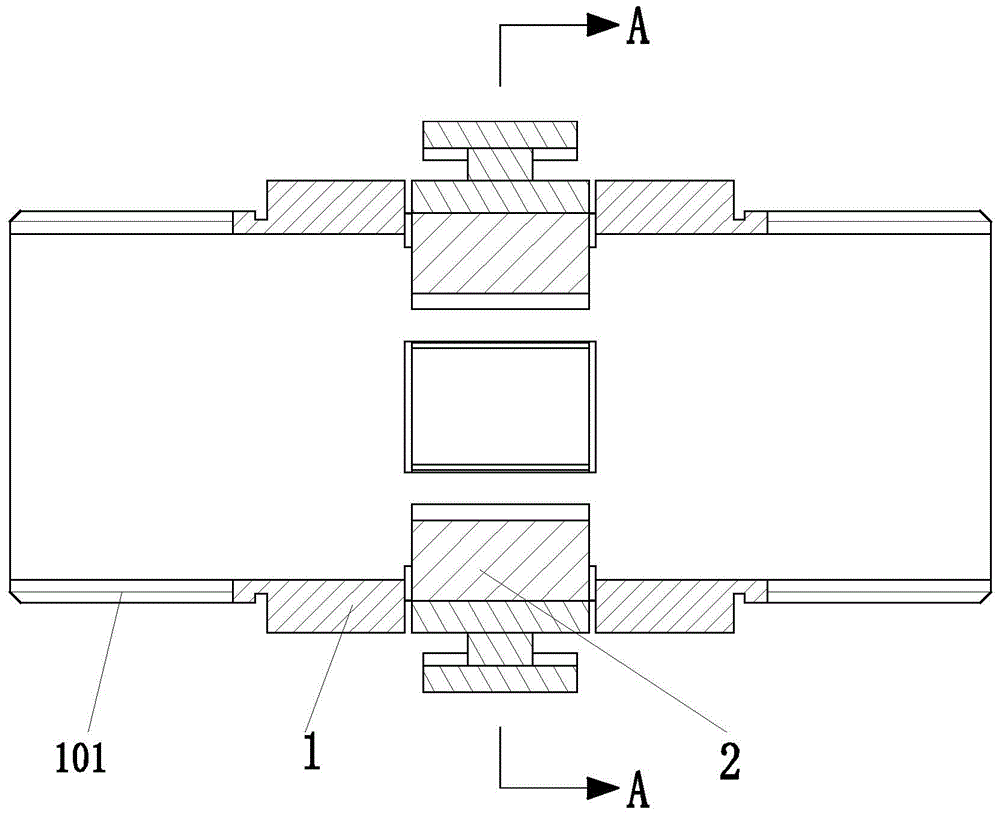
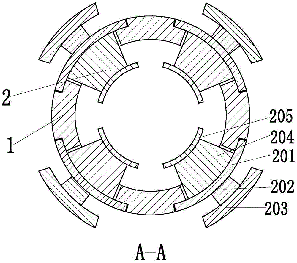
[0014] Such as Figure 1 to Figure 3 As shown, a positioning device for an inner hole positioning fixture includes a positioning cylinder 1 and four positioning claws 2. The positioning cylinder 1 is provided with a cylindrical cavity inside, and both ends of the positioning cylinder 1 are provided with connecting cylinders 101, The connecting cylinder 101 on the left is provided with a left thread, and the connecting cylinder 101 on the right is provided with a right thread. The connecting cylinders 101 on both sides are provided with threads to facilitate installation and disassembly. The middl...


PUM


Abstract

The invention relates to a location device for an inner hole location fixture. The location device comprises a location barrel and four location jaws, wherein a cylindrical cavity is formed in the location barrel, connection barrels are arranged at the both ends of the location barrel, a left thread is arranged on the connection barrel at the left side, and a right thread is arranged on the connection barrel at the right side. The threads are arranged on the connection barrels at the both sides, thus facilitating installation and detachment; four location holes are symmetrically formed in the middle portion of the location barrel, and define the location directions and angles of the location jaws, and location grooves are formed in the upper ends of the location holes; the four location jaws are installed on the location holes of the location barrel respectively. During use, the location device disclosed by the invention is installed on the inner hole location fixture for a pump body, and the location jaws move along the location holes under the action of an external force until the upper ends of the location jaws cling to the inner hole wall of the pump body. The location device disclosed by the invention is capable of assisting the inner hole location fixture for the pump body to realize a location locking function for the inner hole of the pump body, and has the advantages of being low in manufacturing cost, simple and convenient to operate, simple in structure, wide in application range, good in location locking effect, and the like.

Description

Technical field [0001] The invention relates to a positioning fixture for auto parts, in particular to a positioning device for an inner hole positioning fixture. Background technique [0002] Various pump accessories on automobiles include fuel pumps, oil pumps, brake master cylinders, brake cylinders, water pumps, clutch master cylinders, clutch cylinders, etc., and various pump accessories consist of many parts. Among the parts, the processing time is the longest and the most complicated is the pump body. In the process of processing the hole in the pump body, positioning fixtures are needed to realize the positioning of the holes in the pump body, which can be achieved by various positioning fixtures that assist pump body processing. Smooth and high-precision machining of the pump body hole, therefore, the positioning fixture to assist the pump body processing plays a vital role in the pump body hole processing process. In the current market, various pump body hole positioni...

Claims


Application Information

Patent Timeline
Patent Type & Authority Patents(China)
IPC IPC(8): B23Q3/00
CPCB23Q3/00
Inventor 沈德华汪阳
Owner ZHANGJIAGANG DONGDA IND TECH RES INST
Why Eureka
Try Eureka