Method and system for controlling failed position sensor of clutch

A clutch position and control method technology, applied in hybrid vehicles, motor vehicles, transportation and packaging, etc., can solve problems such as inability to shift gears, affecting driving functions, etc.

Active Publication Date: 2015-01-14
WEICHAI POWER CO LTD
View PDF6 Cites 2 Cited by
  • Summary
  • Abstract
  • Description
  • Claims
  • Application Information

AI Technical Summary

Problems solved by technology

[0010] During the actual driving of the vehicle, if the position sensor of the clutch is damaged or a short circuit / open circuit fault occurs, the signal sent by the position sensor cannot be used to judge whether the clutch is in the disengaged state or the engaged state, and thus the gear cannot be shifted, which will affect the driving function

Method used


Image

  • Method and system for controlling failed position sensor of clutch
  • Method and system for controlling failed position sensor of clutch
  • Method and system for controlling failed position sensor of clutch

Examples


Embodiment 1

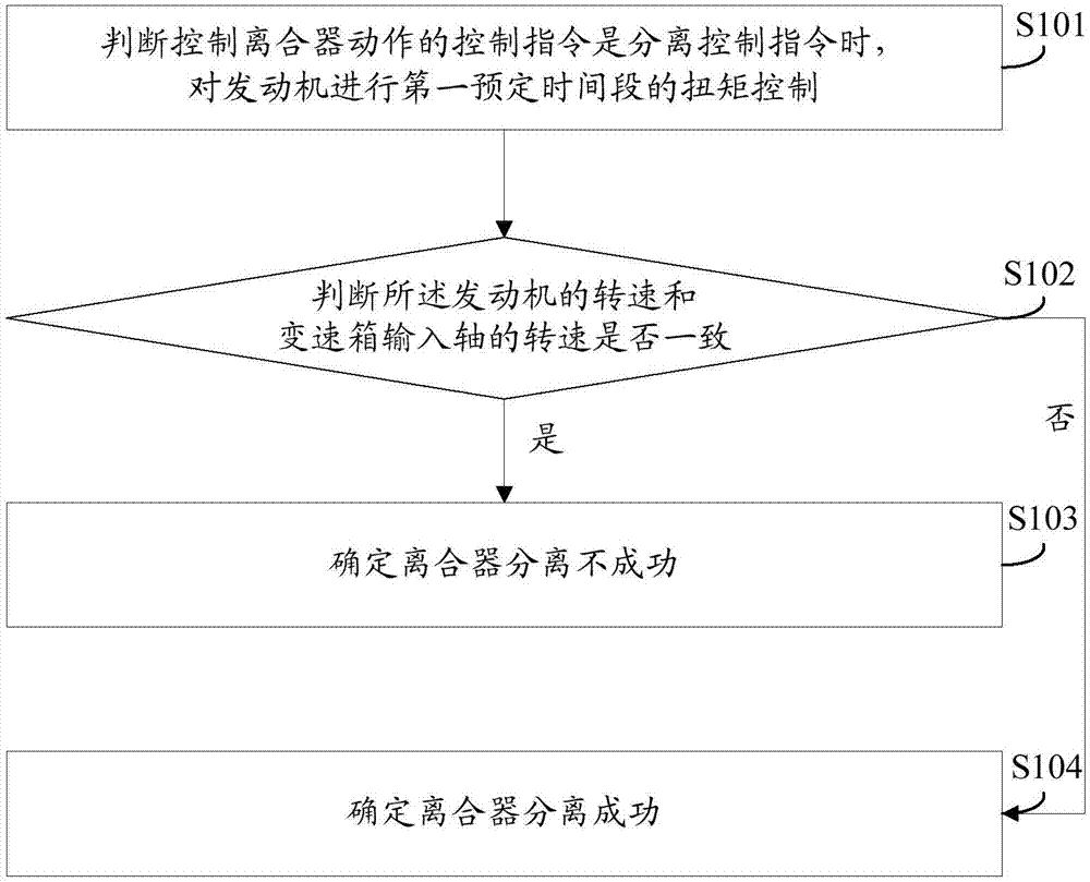
[0060] see figure 1 , which is a flow chart of Embodiment 1 of a control method after the failure of the clutch position sensor provided by the present invention.

[0061] It should be noted that the clutch control in the method provided by the embodiment of the present invention is the same for both the disengagement control instruction and the engagement instruction, and is judged by judging whether the rotational speed of the engine is consistent with the rotational speed of the gearbox input shaft. For the convenience of description and understanding, in the embodiment of the present invention, the judgment of separation and connection is described separately, and the method for judging whether the separation is successful or not is firstly introduced below.

[0062] The control method after the failure of the clutch position sensor provided in this embodiment is applied after the failure of the position sensor of the clutch, and includes the following steps:

[0063] S10...

Embodiment 2

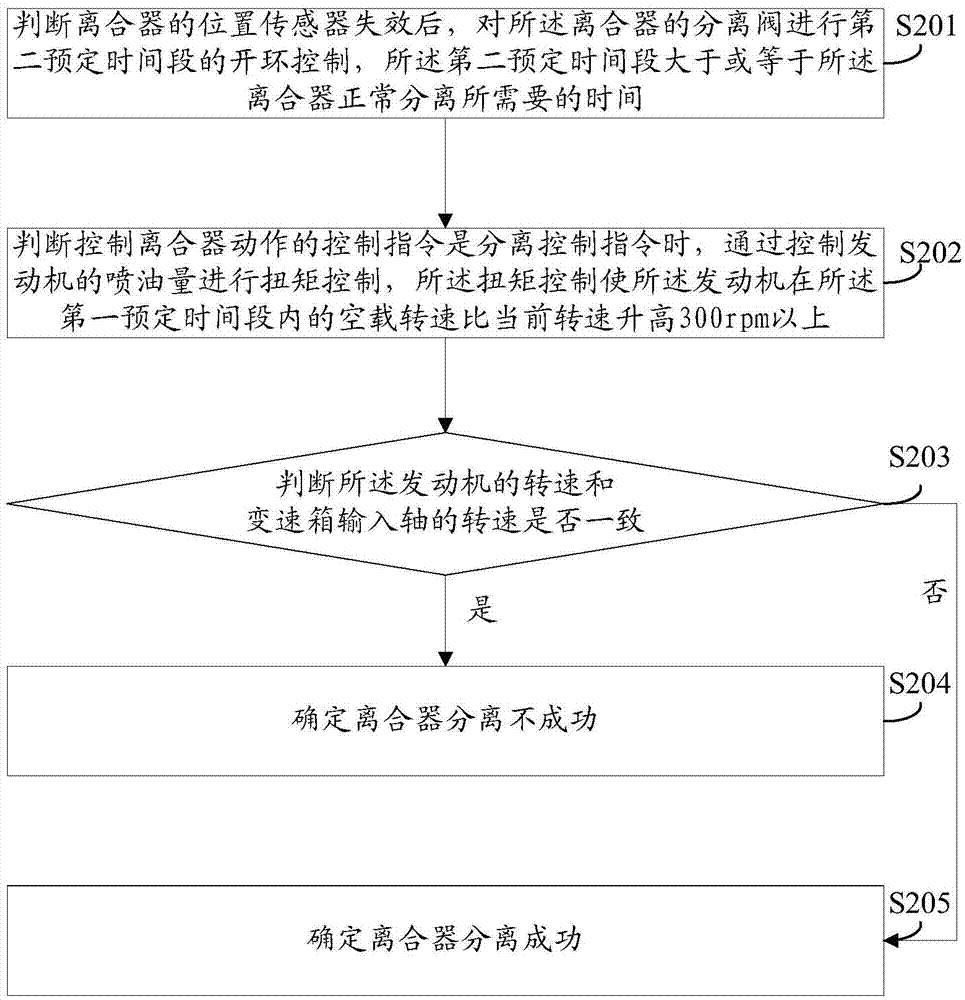
[0073] see figure 2 , which is a flow chart of Embodiment 2 of a control method after the failure of the clutch position sensor provided by the present invention.

[0074] S201: After judging that the position sensor of the clutch is invalid, perform open-loop control on the disengagement valve of the clutch for a second predetermined time period, where the second predetermined time period is greater than or equal to the time required for the clutch to disengage normally.

[0075] It should be noted that when the position sensor fails, the closed-loop control for judging the clutch state by collecting the signal of the position sensor is no longer possible. Therefore, it is necessary to judge the clutch position state through open-loop control.

[0076] The purpose of performing the open-loop control for the second predetermined time period is to allow the clutch to have sufficient time to respond to the command of the open-loop control. The second predetermined period of ti...

Embodiment 3

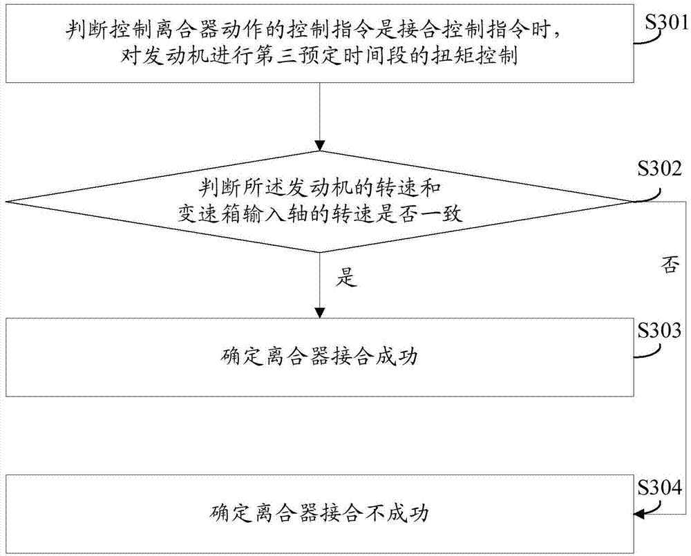
[0087] see image 3 , which is a flow chart of Embodiment 3 of a control method after the failure of the clutch position sensor provided by the present invention.

[0088] The above embodiments are methods for judging whether the clutch is disengaged successfully, and the method for judging whether the clutch is successfully engaged is introduced below.

[0089] The control method after the failure of the clutch position sensor provided in this embodiment is applied after the failure of the position sensor of the clutch, and includes the following steps:

[0090] S301: When it is judged that the control instruction for controlling the clutch action is an engagement control instruction, perform torque control on the engine for a third predetermined time period;

[0091] It is understood that torque control can vary the speed of the engine.

[0092] S302: Determine whether the rotational speed of the engine is consistent with the rotational speed of the gearbox input shaft; if...


PUM


Abstract

The invention provides a method and a system for controlling a failed position sensor of a clutch. The method and the system are applied to the failed position sensor of the clutch. The method comprises the following steps of controlling the torque of an engine in a first preset quantum when determining that a control command of controlling actions of the clutch is a separation control command; judging whether the revolving speed of the engine is consistent to that of an input shaft of a transmission or not; determining that separation of the clutch is unsuccessful if the revolving speed of the engine is consistent to that of the input shaft of the transmission; and determining that separation of the clutch is successful if the revolving speed of the engine is not consistent to that of the input shaft of the transmission. The revolving speed of the engine can be changed by controlling the torque; whether separation of the clutch is successful or not can be judged by judging whether the revolving speed of the engine is consistent to that of the input shaft of the transmission or not when the torque is controlled; and whether reunion of the clutch is successful or not can also be judged by the same way. After the position sensor fails, the current state of the clutch can still be accurately judged, and normal gear shifting running is realized.

Description

technical field [0001] The invention relates to the technical field of clutch control, in particular to a control method and system after a clutch position sensor fails. Background technique [0002] First introduce a few technical terms in this field: [0003] Automatic gearbox: (also known as AMT gearbox) is developed on the basis of mechanical gearbox (manual gearbox), and the automation of shifting action is realized by adding an automatic shift actuator with a controller. [0004] Clutch booster: instead of the action of the driver stepping on the pedal, it provides driving force for the separation and combination of the clutch under the action of the controller. [0005] Solenoid valve: a valve that relies on the electromagnetic force generated by the power supply coil to drive the movable iron core to open and close the disc, and is used to adjust the direction, flow, speed and other parameters of the medium. [0006] Position sensor: In the clutch booster cylinder,...

Claims


Application Information

Patent Timeline
Patent Type & Authority Applications(China)
IPC IPC(8): B60W10/02B60W10/06B60W10/10B60W30/18
CPCB60W10/02B60W10/06B60W20/50B60W2510/0208B60W2510/0638B60W2510/1015B60W2710/021B60W2710/0616B60W2710/0666Y10S903/902
Inventor 董英荣何汉清乔运乾
Owner WEICHAI POWER CO LTD
Why Eureka
Try Eureka