
Pendulum type pumping unit with T-shaped walking beam

A pumping unit and pendulum-type technology, applied in the field of beam pumping units, can solve the problems of high peak torque of pumping units, achieve high mechanical efficiency, eliminate centrifugal force, and reduce peak torque

Inactive Publication Date: 2015-01-14
孙宝利
View PDF8 Cites 7 Cited by
  • Summary
  • Abstract
  • Description
  • Claims
  • Application Information

AI Technical Summary

Problems solved by technology

[0005] The disadvantages of the above-mentioned pumping unit are: since the balance weight is installed on the crank, the balance weight will generate a certain centrifugal force when rotating, and since the angle between the poles is approximately zero, the angle that the crank rotates during the up and down strokes of the pumping unit is basically Equal, in the whole working cycle, the peak torque of the pumping unit is high, and there is also the problem of negative torque

Method used


Image

  • Pendulum type pumping unit with T-shaped walking beam
  • Pendulum type pumping unit with T-shaped walking beam
  • Pendulum type pumping unit with T-shaped walking beam

Examples


Embodiment Construction

[0033] The present invention will be described in further detail below in conjunction with the accompanying drawings, but it is not intended to limit the present invention.

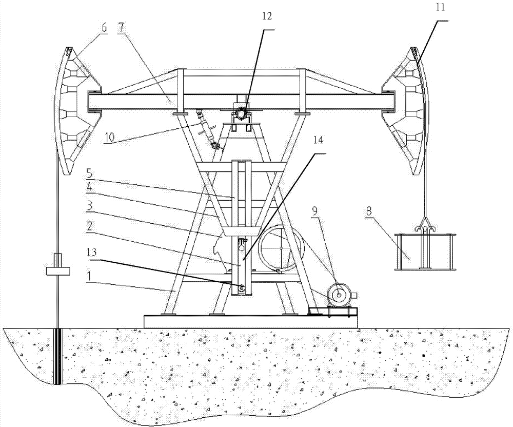
[0034] Such as Figure 3-5 As shown, the present invention provides a beam pumping unit, comprising a frame 1, a crank 2, a swing arm 4, a swing rod 5, a main beam 7, a donkey head and a driving device. Wherein, the swing arm 4, the swing rod 5 and the main beam 7 form a T-shaped beam, wherein, from the positional relationship, the center line of the swing rod 5 is perpendicular to the main beam 7, and is arranged in a T-shaped structure. In the embodiment, the specific The connection structure is as follows: the swing rod 5 is fixed to the swing arm 4, and the swing arm is fixed to the main beam 7, all of which are rigidly connected, such as bolt connection, welding and other connection methods. As a modification, the pendulum can also be directly fixedly connected to the main beam, and the connection c...


PUM


Abstract

The invention provides a pendulum type pumping unit with a T-shaped walking beam. The pumping unit comprises a rack, the T-shaped walking beam, a horse head, a reduction gearbox, a crank and a motor, wherein the T-shaped walking beam is arranged on the rack through a main shaft; the central line of an oscillating bar is perpendicular to a main beam to form the T-shaped walking beam in rigid connection, and the transmission angle of the oscillating bar and the main beam during movement is equal to 90 degrees all the time; an output shaft of the reduction gearbox is positioned below the main shaft; the crank is arranged on the output shaft of the reduction gearbox and is provided with a striking gear; the striking gear is matched with the oscillating bar to change the rotation movement of the crank into arc movement of the oscillating bar so as to drive the up-down swing of the main beam. The counterweight balance moment is stable, the peak torque of the pumping unit can be obviously reduced, the negative torque is eliminated, the stability is enhanced, and the energy saving effect is improved.

Description

technical field [0001] The invention relates to the field of oil production machinery, in particular to a beam pumping unit. Background technique [0002] The beam pumping unit, as the surface power equipment of the downhole oil pump, is a main mechanical oil recovery equipment. The common structure of the pumping unit is generally that the frame is located in the middle of the beam, and the loads on both ends of the beam are relatively balanced when the pumping unit is working, so that the frame runs smoothly; the crank adopts a conventional bar crank and is connected with a balance block. The crank linkage mechanism and the donkey head are respectively located on both sides of the frame, and the crank and the beam are transmitted through rigid connection or soft connection to transmit power and torque. [0003] Such as figure 1 As shown, the power can be transmitted between the crank and the beam through the soft connection of the wire rope. For example, a double donkey...

Claims


Application Information

Patent Timeline
Patent Type & Authority Applications(China)
IPC IPC(8): E21B43/00
CPCE21B43/00
Inventor 孙宝利
Owner 孙宝利
Features
  • Generate Ideas
  • Intellectual Property
  • Life Sciences
  • Materials
  • Tech Scout
  • Unparalleled Data Quality
  • Higher Quality Content
  • 60% Fewer Hallucinations
Learn More