Oil catch

An oil block and oil intake technology, applied in the direction of engine sealing, engine components, mechanical equipment, etc., can solve the problems of poor oil block sealing and easy oil leakage, and achieve good sealing effect, long service life, and reduce the effect of backflow.

Active Publication Date: 2015-01-14
SUZHOU NUCLEAR POWER RES INST +2
View PDF8 Cites 6 Cited by
  • Summary
  • Abstract
  • Description
  • Claims
  • Application Information

AI Technical Summary

Problems solved by technology

[0003] The technical problem to be solved by the present invention is to provide an oil retainer with good sealing performance that can prevent oil leakage from the rotating shaft of the generator in view of the defects of the prior art that the above-mentioned oil retainer has poor sealing performance and is prone to oil leakage.

Method used


Image

  • Oil catch
  • Oil catch
  • Oil catch

Examples


Embodiment Construction

[0021] In order to have a clearer understanding of the technical features, purposes and effects of the present invention, the specific implementation manners of the present invention will now be described in detail with reference to the accompanying drawings.

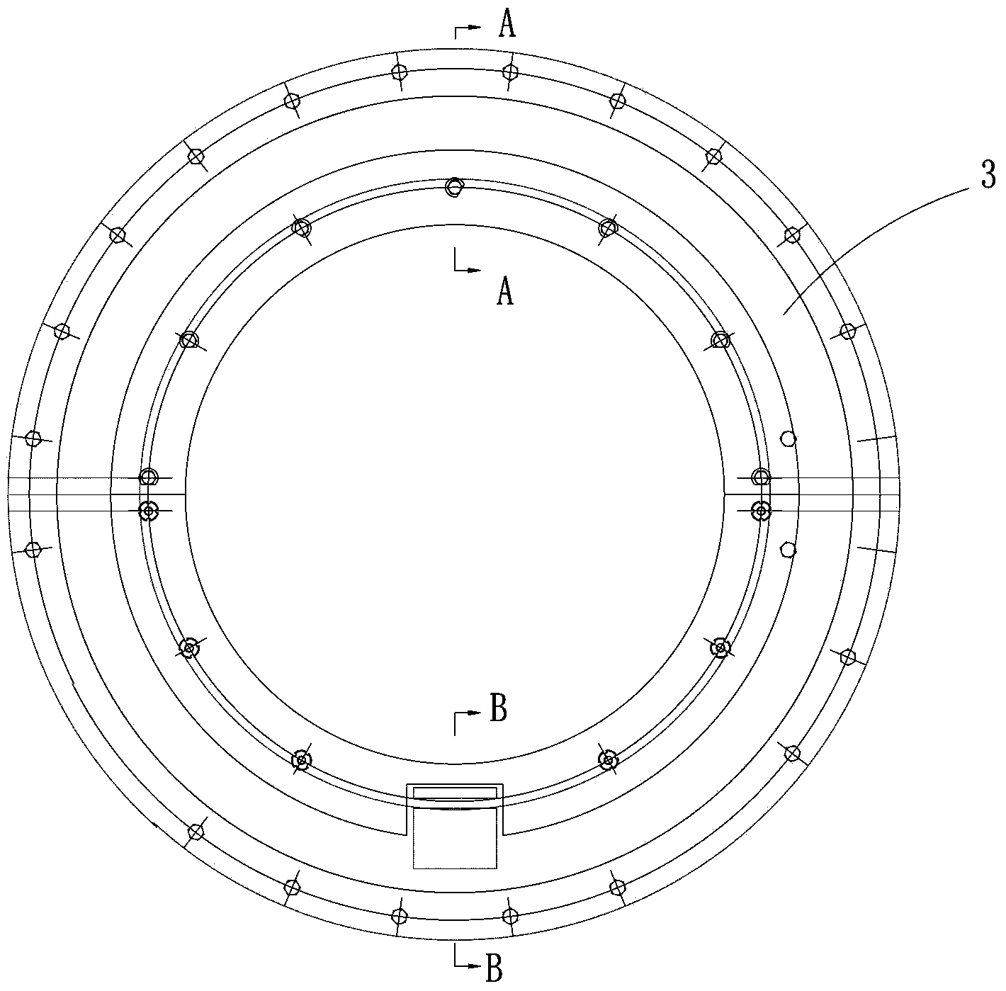
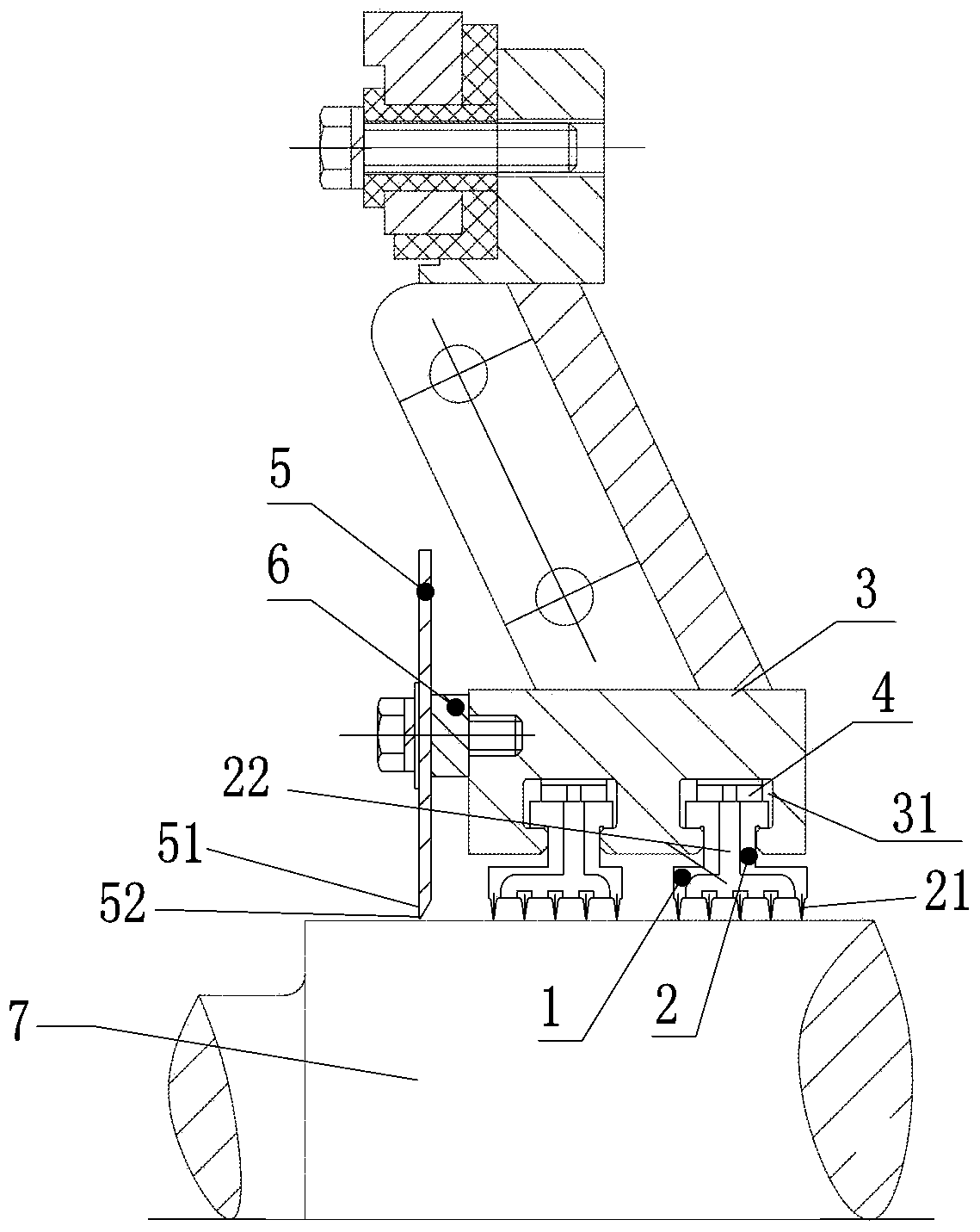
[0022] like figure 1 shown and combined with figure 2 . The oil baffle in this embodiment includes an oil baffle ring 3 sleeved on the rotating shaft 7, and an inner oil baffle plate 5 fitted on the outer periphery of the rotating shaft 7, and the inner oil baffle plate 5 is fixedly connected to the inner side of the oil baffle ring 3 , A gap is formed between the inner oil baffle 5 and the rotating shaft 7, the inner oil baffle 5 is used to block the oil attached to the rotating shaft 7 on the oil inlet path, and make the oil enter the oil baffle ring 3 below through the gap. The interval of the gap is L, 0.4≤L≤0.6 mm.

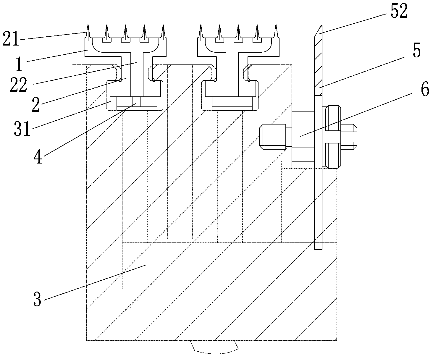
[0023] The oil retainer also includes an outer ring 1 and an inner ring 2. The inner side of th...


PUM


Abstract

The invention discloses an oil catch which comprises an oil catch ring (3) arranged on a rotating shaft (7) in a sleeving mode and an inner oil baffle plate (5) sleeving the periphery of the rotating shaft (7). The inner oil baffle plate (5) is fixedly connected to the inner side of the oil catch ring (3), a gap is formed between the oil baffle plate (5) and the rotating shaft (7), and the inner oil baffle plate (5) is used for blocking oil attached to the rotating shaft (7) on an oil inlet path and enabling the oil to enter the position below the oil catch ring (3) through the gap. The oil catch has the advantages that due to the inner oil baffle plate fixedly connected to the inner side of the oil catch ring, the intercepting ability is improved, namely oil attached to the rotating shaft is firstly blocked by the inner oil baffle plate and then enters the gap, and the sealing effect is good.

Description

technical field [0001] The invention relates to an oil sealing device, and more specifically, relates to an oil baffle installed at the rotating shaft of a generator for oil sealing and preventing the oil attached to the rotating shaft from being thrown out. Background technique [0002] Generators generally include a rotating shaft, but during the operation of the generator, with the rotation of the rotating shaft, the oil (such as lubricating oil) attached to the rotating shaft is easily thrown from the inside of the generator to the outside of the generator, which is not only harmful to the operation of the generator itself , and the oil thrown outside the generator is also likely to pollute other equipment, causing serious pollution to other equipment. In some cases, the oil thrown outside the generator will also cause problems such as short circuits of other equipment. In view of the above problems, the solution in the prior art is generally to insert an oil stopper on ...

Claims


Application Information

Patent Timeline
Patent Type & Authority Applications(China)
IPC IPC(8): F16J15/16
CPCF16J15/16
Inventor 杨武朱青海贾凯利周富涛孙琦
Owner SUZHOU NUCLEAR POWER RES INST
Why Eureka
Try Eureka