Installation structure of lamp electronic component and lamp

An electronic device and installation structure technology is applied in the field of the installation structure of the electronic device of the lamp, which can solve the problems of inconvenient loading and unloading of the electronic device, destroying the sealing effect of the lamp, and increasing the manufacturing cost of the lamp, so as to improve the efficiency and flexibility, and avoid mutual interference. , the effect of low manufacturing cost

Inactive Publication Date: 2015-01-14
OCEANKING DONGGUAN LIGHTING TECH +2
View PDF9 Cites 1 Cited by
  • Summary
  • Abstract
  • Description
  • Claims
  • Application Information

AI Technical Summary

Problems solved by technology

This installation structure is not convenient for loading and unloading of electronic devices, and is not convenient for lamp maintenance. Moreover, for lamps with high sealing requirements, it is obviously not advisable to open holes on the lamp housing, because this will damage the internal structure of the lamp. sealing effect
In addition, in the above installation structure, screw holes or holes at different positions need to be provided for different electronic devices, which results in low versatility of the lamp housing, and different lamp housings need to be manufactured for different electronic devices, which improves the manufacturing efficiency of the lamp. cost

Method used


Image

  • Installation structure of lamp electronic component and lamp
  • Installation structure of lamp electronic component and lamp
  • Installation structure of lamp electronic component and lamp

Examples


Embodiment Construction

[0022] In order to make the object, technical solution and advantages of the present invention clearer, the present invention will be further described in detail below in conjunction with the accompanying drawings and embodiments. It should be understood that the specific embodiments described here are only used to explain the present invention, not to limit the present invention.

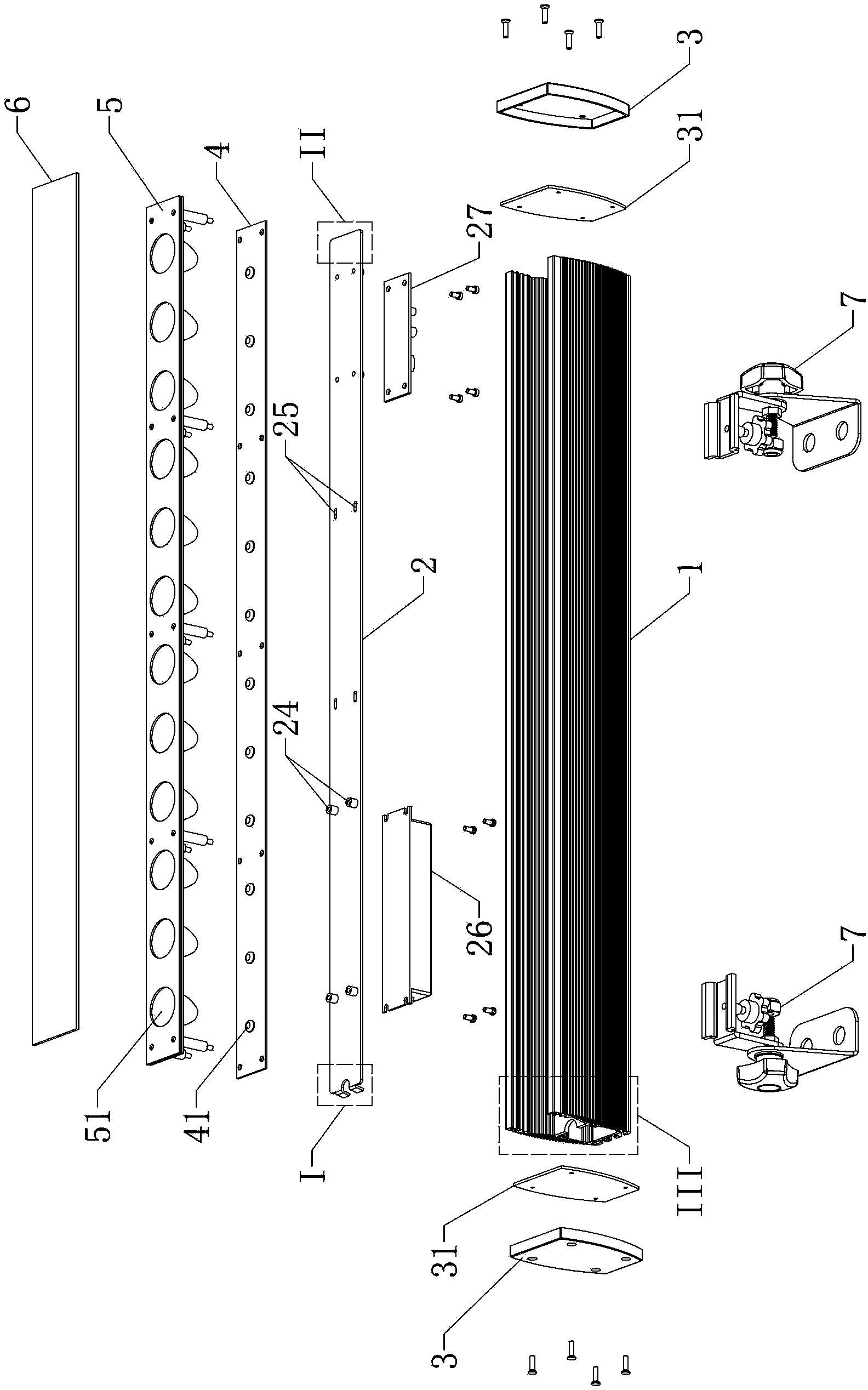
[0023] see figure 1 , the embodiment of the present invention provides a mounting structure for lamp electronic components, including a lamp housing 1, a mounting plate 2 for loading electronic devices, and an end cover 3, the lamp housing 1 has a groove with two ends open, the Both sides of the inner wall of the cavity of the lamp housing 1 are symmetrically provided with first slots 11 for inserting and fixing the mounting plate 2 (see Figure 5 ), the mounting plate 2 is inserted into the first slot 11 , and the end caps 3 are provided at both ends of the lamp housing 1 . First, install the el...


PUM


Abstract

The invention provides an installation structure of a lamp electronic component. The installation structure comprises a lamp shell, an installation plate and end covers, wherein the installation plate is used for installing the electronic component. A groove is formed in the lamp shell, the two ends of the groove are open, first insertion grooves are symmetrically formed in the two sides of the inner wall of a cavity of the groove of the lamp shell, and the installation plate is inserted into and fixed to the first insertion grooves. The end covers are arranged at the two ends of the lamp shell. The installation structure is convenient and rapid to install and detach and stable in structure, and efficiency and flexibility of installing and maintaining a lamp are improved. The invention further provides the lamp. The lamp comprises the installation structure of the lamp electronic component, a lamp plate, a lens carrier plate and a light-transmitting plate, wherein light sources are installed on the lamp plate, and lens assemblies are installed on the lens carrier plate. The lens carrier plate is fixedly connected with the lamp plate, a second insertion groove is formed in the inner wall of the lamp shell, and the lens carrier plate is inserted into the second insertion groove. A partitioning plate is arranged inside the lamp shell and divides the cavity of the groove into an electronic component containing cavity and a light source containing cavity, wherein the light-transmitting plate is arranged on a notch of the lamp shell. The lamp is convenient to install and detach and flexible and convenient to operate.

Description

technical field [0001] The invention belongs to the technical field of lamps, and in particular relates to an installation structure of electronic components of a lamp and a lamp adopting the structure. Background technique [0002] Electronic devices, such as power supplies or drive circuit boards, are generally installed inside the lamps. In the prior art, the electronic devices are generally installed and fixed in this way: screw holes or holes are directly provided in the lamp housing of the lamp, and the electronic devices are fastened to the screw holes or holes by bolts or screws. This installation structure is not convenient for loading and unloading of electronic devices, and is not convenient for lamp maintenance. Moreover, for lamps with high sealing requirements, it is obviously not advisable to open holes on the lamp housing, because this will damage the internal structure of the lamp. Sealing effect. In addition, in the above installation structure, screw hol...

Claims


Application Information

Patent Timeline
Patent Type & Authority Applications(China)
IPC IPC(8): F21V17/10F21Y101/02
CPCF21V23/00F21V15/02F21V17/10F21V21/14F21Y2101/00
Inventor 周明杰彭冬来
Owner OCEANKING DONGGUAN LIGHTING TECH
Why Eureka
Try Eureka