Display panel and display device
A display panel and display device technology, which is applied in nonlinear optics, instruments, optics, etc., can solve the problems of display panels not being able to display normally, display panel screen effects, etc., and achieve good screen display effects and good display effects
- Summary
- Abstract
- Description
- Claims
- Application Information
AI Technical Summary
Problems solved by technology
Method used
Image
Examples
Embodiment 1
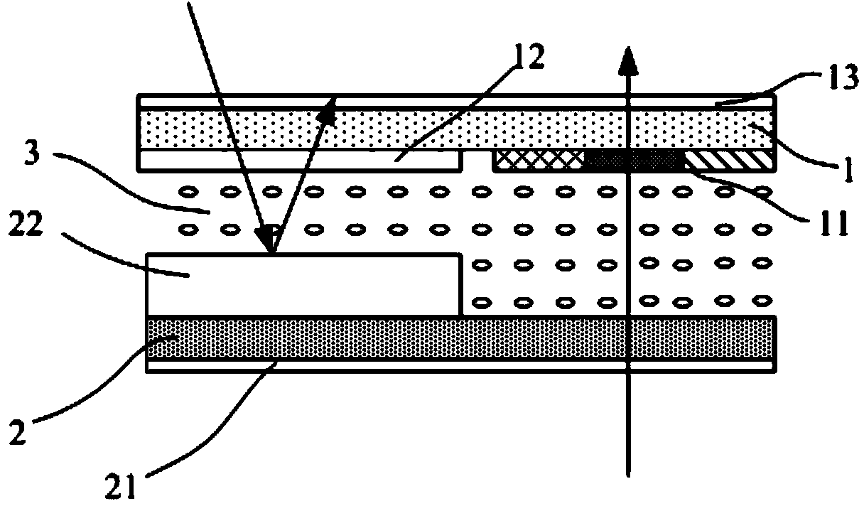
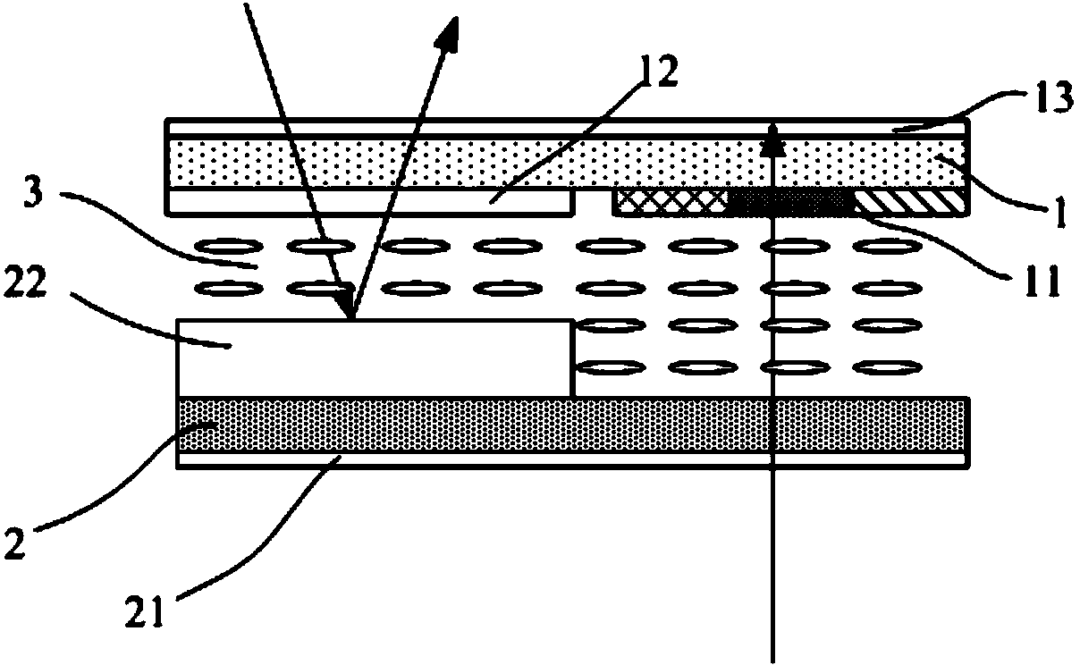
[0028] combine figure 1 and 2 As shown, the present embodiment provides a display panel, the display panel is an IPS type or ADS type (ADSDS; referred to as ADS, ADvanced Super Dimension Switch, advanced super dimension field switching technology) display panel, those skilled in the art can understand that Although the electrode structures of the IPS type or ADS type display panels are different, the types of electric fields formed by the electrode structures of the two are similar and both are horizontal electric fields. The upper plate-shaped electrode and the strip-shaped electrode, the strip-shaped electrode is arranged above the plate-shaped electrode, and both are electrically insulated; the electric field structure of the IPS type display panel includes first strip-shaped electrodes arranged on the array substrate 2 at intervals and insulated and the second strip electrode. Moreover, the liquid crystal molecules used in the display panels of the two modes are positive...
Embodiment 2
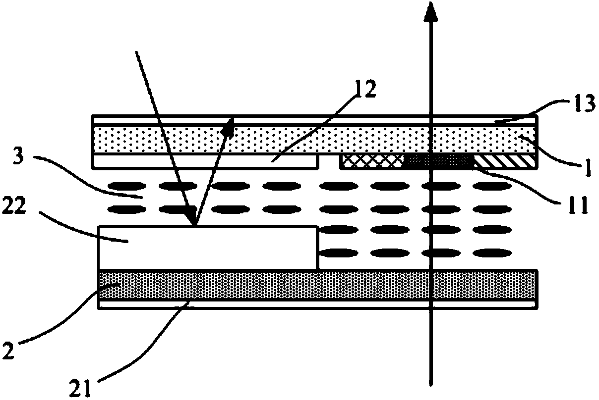
[0032] combine image 3 and 4 As shown, the present embodiment provides a display panel, the display panel is a VA or TN display panel, those skilled in the art can understand that, the electric field of the VA or TN display panel is a vertical electric field, and the VA display panel As an example for illustration, the electrode structure includes a first sheet electrode disposed on the color filter substrate 1 and a second sheet electrode disposed on the array substrate 2, and the liquid crystal molecules used are negative liquid crystals.
[0033] The color filter substrate 1 in the display panel of this embodiment includes a plurality of pixel units, each pixel unit includes a transmission area and a reflection area, and a color filter 11 is formed in the transmission area; A reflective structure 22 is provided on one side of one side and at a position corresponding to the reflective area, and the thickness of the reflective structure 22 is half of the thickness of the co...
Embodiment 3
[0041] This embodiment provides a display device, which includes the above-mentioned display panel, and a backlight source for providing a backlight for the display panel. Of course, other known structures such as a power supply unit and a drive control unit should also be included, which will not be described in detail here.
[0042] The display device in this embodiment can be a liquid crystal display device. In addition, it can also be any product or component with a display function such as electronic paper, mobile phone, tablet computer, television, monitor, notebook computer, digital photo frame, and navigator.
[0043] Since the display device of this embodiment includes the above-mentioned display panel, its display effect is better.
PUM
 Abstract
Description
Claims
Application Information
 - R&D
- Intellectual Property
- Life Sciences
- Materials
- Tech Scout
- Unparalleled Data Quality
- Higher Quality Content
- 60% Fewer Hallucinations
Browse by: Latest US Patents, China's latest patents, Technical Efficacy Thesaurus, Application Domain, Technology Topic, Popular Technical Reports.
© 2025 PatSnap. All rights reserved.Legal|Privacy policy|Modern Slavery Act Transparency Statement|Sitemap|About US| Contact US: help@patsnap.com


