Self-adaptive power system and power supply method

A technology of self-adaptive power supply and power supply, which is applied in the direction of control/regulation system, adjustment of electrical variables, instruments, etc., can solve the problems of occupying a large volume, inconvenient to carry, complex structure, etc., and achieve the effect of improving portability

Active Publication Date: 2015-01-14
广东夏野日用电器有限公司
7 Cites 5 Cited by

AI-Extracted Technical Summary

Problems solved by technology

[0009] At the same time, if the user owns multiple different electronic devices at the same time, they need multiple different power adapters or mobile power supplies, or power adapters with multi...

Abstract

The invention relates to a self-adaptive power system and a power supply method of the self-adaptive power system. According to the self-adaptive power system and the power supply method, a power interface of a device is adopted to send identification information corresponding to device power requirements to a power supply unit, the power supply unit changes the voltage level of output power according to the identification information, and therefore self-adaptive power supply is achieved. By means of the system and method, a power supply can be accurately matched with the device, power system output can be changed in a self-adaptive mode according to the input power requirement of the known device, and the power system output also can be changed through external control. Portability, universality and flexibility of the power system are improved.

Application Domain

Electric variable regulation

Technology Topic

Self adaptiveEngineering +2

Image

  • Self-adaptive power system and power supply method
  • Self-adaptive power system and power supply method
  • Self-adaptive power system and power supply method

Examples

  • Experimental program(4)

Example Embodiment

[0073] Example one
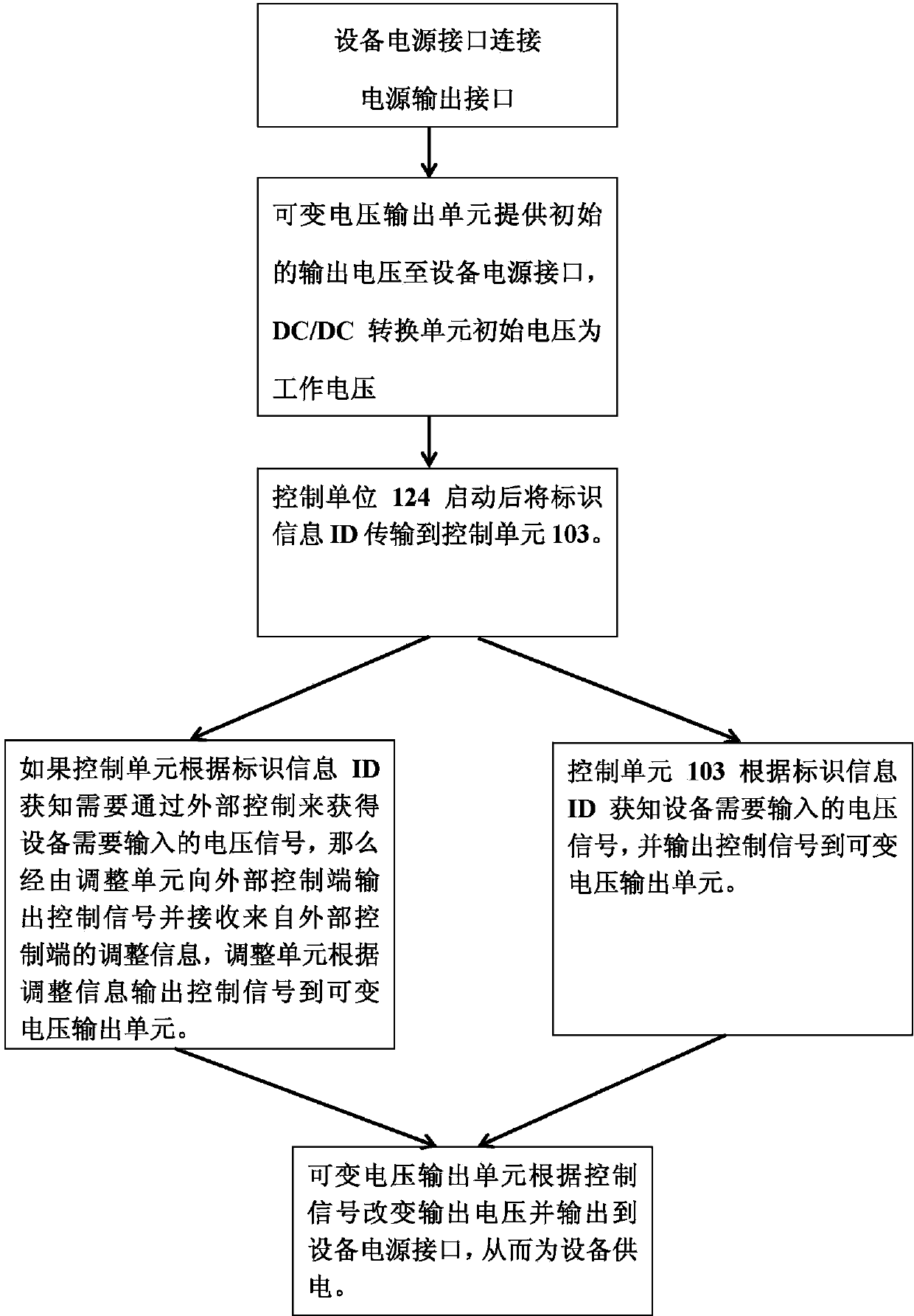
[0074] Since different electronic devices have different rated input voltages, in order to achieve an adaptive change in the output voltage of the power supply system, identification information needs to be provided from the device end to the power source end to indicate the required voltage signal level.
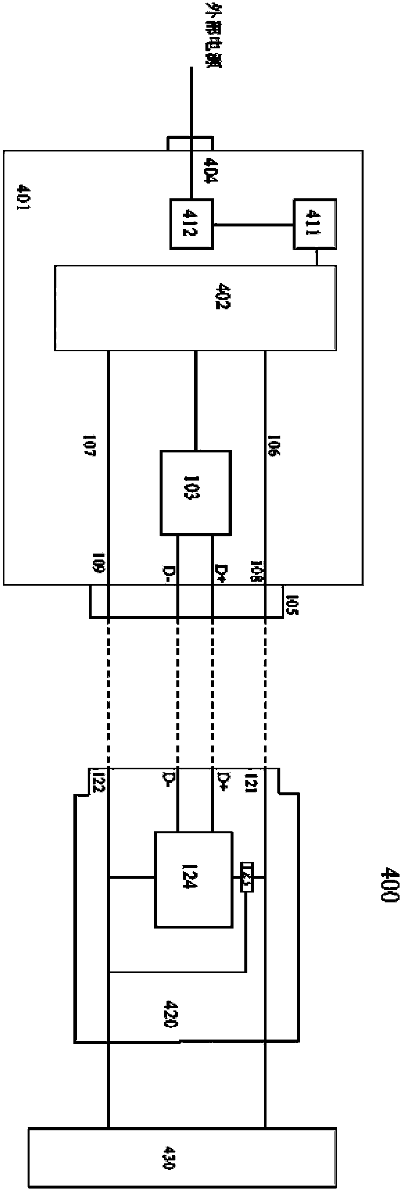
[0075] Fig. 1 shows the adaptive power supply system of the first embodiment of the present invention. The adaptive power supply system 100 includes a power supply unit 101, a device power interface 120, and a device 130.
[0076] The device power interface 120 includes a power terminal VCC121, a ground voltage terminal GND122, data terminals D+ and D-, a voltage stabilizing module 123 and a control unit 124. The power terminal VCC121 and the ground voltage terminal GND122 are connected to the power input terminal of the device 130.
[0077] The input of the voltage stabilizing module 123 is connected to the power terminal VCC121 and the ground voltage terminal GND122, and its output terminal is connected to the control unit 124 so as to provide the control unit 124 with a fixed operating voltage.
[0078] The power terminal of the control unit 124 is respectively connected to the output of the voltage stabilizing module 123 and the ground voltage terminal GND122, and its data output terminal is connected to the data terminals D+ and D- of the device power interface 120, so as to output the internally stored identification information ID. The ID information indicates the rated input power information of the device 130. For example, when ID=1, the device 130 needs an input/charge voltage of 3.7V; when ID=2, the device 130 needs an input/charge voltage of 5V; when ID=3, Then the device 130 needs an input/charging voltage of 12V.
[0079] The power supply unit 101 includes a variable voltage output unit 102, a control unit 103, an external power input terminal 104 and a power output interface 105.
[0080] The variable voltage output unit 102 includes a power input terminal, a power output terminal and a control terminal. Its power input terminal receives input from an external power source (such as 100-240V mains) via the external power input terminal 104, and its power output terminal is connected to the power terminal VCC108 and ground of the power output interface 105 through the power line 106 and the ground line 107 The voltage terminal GND109 can output voltage to the device via the power output interface 105 according to the information of the control terminal.
[0081] The variable voltage output unit 102 can be composed of UC3842AN and its peripheral circuits, and the control unit can be composed of C8051F320/STM32F103/PIC18F4550 and its peripheral circuits. Obviously, it can also be composed of other circuits known to those skilled in the art.
[0082] The input terminal of the control unit 103 is connected to the data terminals D+ and D- of the power output interface 105, and the output terminal of the control unit 103 is connected to the control terminal of the variable voltage output unit 102, so that the data from the data terminals D+ and D- The identification information ID controls the output of the variable voltage output unit 102. For example, the control unit 103 stores a mapping table of the identification information ID and the corresponding voltage and the corresponding voltage control signal. When the received identification information ID=1, the corresponding voltage control signal indicates The variable voltage output unit 102 will be controlled to output a voltage of 3.7V; when the identification information ID=2 is received, the corresponding voltage control signal indicates that the variable voltage output unit 102 will be controlled to output a 5V voltage; when the identification information ID=3 is received , The corresponding voltage control signal indicates that the output voltage of 10V of the variable voltage output unit 102 will be controlled.
[0083] Figure 1B Shows the power supply method of the adaptive power system. When the device needs power input, the device power interface 120 is connected to the power output interface 105, and the power terminal VCC, the ground voltage terminal GND, and the data terminals D+ and D- of the two interfaces are connected correspondingly.
[0084] The variable voltage output unit 102 provides the initial output voltage to the power terminal VCC and the ground voltage terminal GND of the device power interface 120 and the power output interface 105, so that the voltage stabilizing module 123 provides a working voltage for the control unit 124 by converting the initial voltage.
[0085] After the control unit 124 is started, the stored identification information ID is transmitted to the control unit 103 via the data terminals D+ and D- of the device power interface 120 and the power output interface 105, where the identification information ID represents the voltage signal that the device needs to input.
[0086] The control unit 103 learns the voltage signal that the device needs to input according to the identification information ID, and outputs the control signal to the variable voltage output unit 102.
[0087] The variable voltage output unit 102 changes the output voltage according to the control signal and outputs the voltage signal that the device needs to input to the power supply terminal VCC of the device power interface 120 and the power output interface 105, thereby powering the device.
[0088]

Example Embodiment

[0089] Example two
[0090] Although the device power interface device connected to the device can provide indication information to the power supply unit, since the control unit in the device power interface only stores one ID information, it can only be used for a type of electronic device that requires the same input power. In order to be suitable for electronic devices with different voltage requirements, in one case, the ID information stored in the control unit of the device power interface needs to be changed to correspond to different voltage signals, so that the device power interface device can be used for power supply of different electronic devices. However, this requires additional modification devices to modify the ID information.
[0091] figure 2 The adaptive power supply system of the second embodiment of the present invention is shown. The adaptive power supply system 200 includes a power supply unit 201, a device power interface 220, and a device 230.
[0092] The power supply unit 201, the connection relationship between the device power interface 220 and the device 230, and the structure of the power supply unit 201 are the same as those in the first embodiment, and will not be repeated here.
[0093] The difference from the first embodiment is that the device power interface 220 includes a power terminal VCC221, a ground voltage terminal GND222, data terminals D+ and D-, and a voltage stabilizing module 223. The input of the voltage stabilizing module 223 is connected to the power terminal VCC121 and the ground voltage terminal GND122.
[0094] At the same time, the device power interface 220 also has a slot, which can be used to insert different circuit boards in a replaceable manner, and the slot has four contacts A, B, C, and D. The working voltage output end of the voltage stabilizing module 223 is connected to the first contact A in the slot. At the same time, the ground voltage terminal GND222, the data terminals D+ and D- are respectively connected to the second, third, and fourth contacts B, C, and D in the slot.
[0095] The control unit 224 is integrated on the external circuit board card corresponding to the above-mentioned slot shape and size. It has a working power terminal, a ground voltage terminal and two data terminals, which are respectively connected to the four contacts A'on the circuit board card, B', C', D'. There may be a plurality of such circuit board cards, and the control unit 224 in different board cards stores different identification information IDs to represent different voltage signal levels.
[0096] The difference between the power supply method of the adaptive power supply system in the second embodiment and the first embodiment is that before using the device power interface 220 to connect the power supply unit 201 and the device 230, it will first include the signal level corresponding to the voltage signal required by the device. The circuit board card of the identification information ID is inserted into the device power interface 220, so that the contacts A, B, C, D are electrically connected with A', B', C', D', so that the control unit 224 can receive through the power terminal The working power signal and the stored identification information ID are sent through the data terminal, and then the power supply unit 201 and the device 230 are connected. Therefore, when different electronic devices use the same device power interface to receive power signals, the circuit board cards containing different identification information IDs can be replaced to prompt the power supply unit 201 to provide power voltage signals corresponding to different identification information IDs.
[0097] For example, when a circuit board card with ID=1 is inserted, it means that the device needs an input/charging voltage of 3.7V; when a circuit board card with ID=2 is inserted, it means that the device needs an input/charging voltage of 5V; When a circuit board card with ID=3 is inserted, it means that the device requires 12V input/charging voltage.
[0098]

Example Embodiment

[0099] Example three
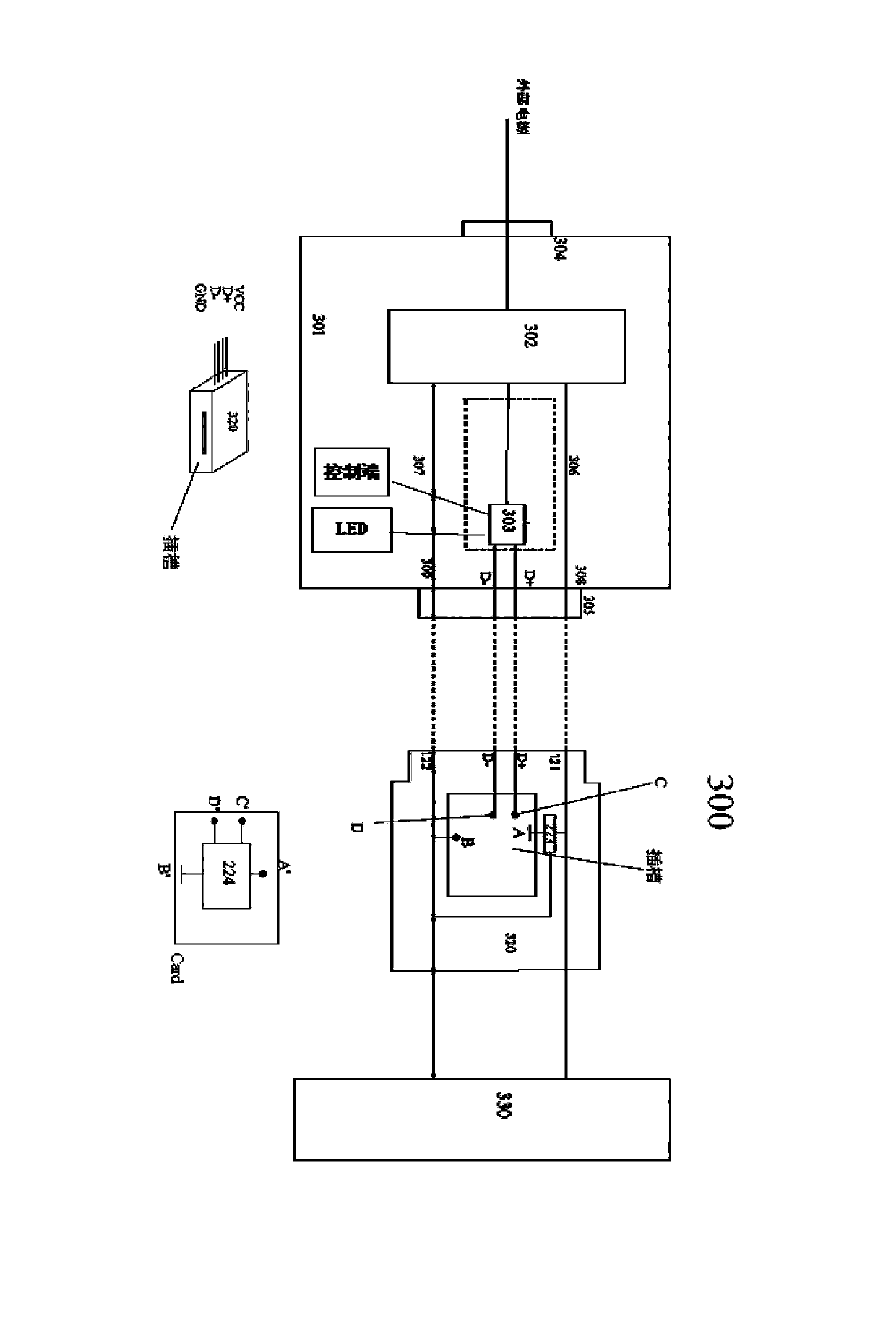
[0100] In the second embodiment, although the plug-in device power interface can supply power to different electronic devices by replacing the circuit board card with different ID information, so that one device power interface can supply power to different electronic devices, but due to the wide variety of electronic devices, at the same time It is not easy to know the power requirements of all known or unknown electronic devices. This may make users need to carry a large number of circuit board cards, or the power system cannot be used because there is no corresponding circuit board card.
[0101] Figure 3A The adaptive power supply system of the third embodiment of the present invention is shown. The adaptive power supply system 300 includes a power supply unit 301, a device power interface 320, and a device 330.
[0102] The connection relationship between the power supply unit 301, the device power interface 220 and the device 230 is the same as in the first and second embodiments, and the internal structure of the device power interface 220 is the same as in the second embodiment (or can be the same as in the first embodiment, That is, the device power interface with fixed internal connection relationship is adopted), and the description will not be repeated here.
[0103] Different from the first and second embodiments, the power supply unit 301 includes a variable voltage output unit 302, a control unit 303, an external power input terminal 304, and a power output interface 305. The control unit 303 is connected to an external display terminal (such as LED ) And the external control terminal.
[0104] As in the first embodiment, the variable voltage output unit 302 includes a power input terminal, a power output terminal, and a control terminal. Its power input terminal receives input from an external power source (such as 100-240V mains) via the external power input terminal 104, and its power output terminal is connected to the power terminal VCC308 and ground of the power output interface 305 through the power line 306 and the ground line 307 The voltage terminal GND309 can output voltage to the device via the power output interface 305 according to the information of the control terminal.
[0105] The input terminal of the control unit 303 is connected to the data terminals D+ and D- of the power output interface 105, and the output terminal of the control unit 303 is connected to the control terminal of the variable voltage output unit 102, so that the data from the data terminals D+ and D- The identification information ID controls the output of the variable voltage output unit 102.
[0106] At the same time, the control unit 303 is connected to an external display terminal (such as LED) and an external control terminal (such as a keyboard or an external computer) through an interface, and can be used to display output information from the control unit 303 through the external display terminal, and to receive information from the external control terminal. External input information. Further, the control unit 303 can also be connected to an external control terminal through a wired/wireless interface, which facilitates the exchange of information between the control unit 303 and the external control terminal.
[0107] For example, if there is no corresponding circuit board card that can prompt the device to input the power supply voltage, then insert the circuit board card with the identification information ID of a specific value (or use the device power interface with the specific ID information stored in the first embodiment) This specific value indicates that the input voltage of the electronic device cannot be determined by the device power interface but needs to be determined from the external control terminal. Then when the device power interface is connected to the device and the power supply unit, the control unit 303 receives the specific identification information ID (for example, ID=0) from the device power interface, which means that the input voltage of the electronic device cannot be determined by the device power interface and needs to be determined by For external control, the control unit 303 will output a prompt message to the external display terminal to indicate that the output voltage signal needs to be adjusted. At the same time, it can also output a prompt message to the external control terminal to indicate that the output voltage signal needs to be adjusted. Then the control unit 303 receives the signal from the external control terminal. After the voltage control signal (for example, the external control terminal determines that the device requires a 12V input voltage, then it transmits a control signal representing the 12V output voltage), the control unit 303 provides a control signal to the variable voltage output unit 102 to make the variable voltage output unit 102 change The initial output voltage reaches the voltage required by the device (for example, 12V).
[0108] Figure 3B The power supply method of the adaptive power supply system of the third embodiment is shown. When the device needs power input, the device power interface 320 is connected to the power output interface 305, and the power terminal VCC, the ground voltage terminal GND, and the data terminals D+ and D- of the two interfaces are connected correspondingly. Obviously, if the adaptive power system adopts the method in which the circuit board card can be inserted in the second embodiment, then the method in the second embodiment can also be used to insert the circuit board card into the device power interface before this step.
[0109] The variable voltage output unit 302 provides the initial output voltage to the power terminal VCC and the ground voltage terminal GND of the device power interface 320 and the power output interface 305, so that the voltage stabilizing module 323 provides a working voltage for the control unit 324 by converting the initial voltage.
[0110] After the control unit 324 is started, the stored identification information ID is transmitted to the control unit 303 via the data terminals D+ and D- of the device power interface 320 and the power output interface 305, where the identification information ID represents the voltage signal that the device needs to input.
[0111] If the control unit 303 learns the voltage signal that the device needs to input according to the identification information ID, and outputs the control signal to the variable voltage output unit 302. If the control unit 303 learns from the identification information ID that the voltage signal that the device needs to input needs to be obtained through external control, then it outputs the control information to the external display terminal or the external control terminal, and the control unit 303 receives the adjustment information from the external control terminal and outputs it according to the adjustment information The control signal is sent to the variable voltage output unit 302.
[0112] The variable voltage output unit 302 changes the output voltage according to the control signal and outputs the voltage signal that the device needs to input to the power terminal VCC of the device power interface 320 and the power output interface 305, thereby supplying power to the device.
[0113]

PUM

no PUM

Description & Claims & Application Information

We can also present the details of the Description, Claims and Application information to help users get a comprehensive understanding of the technical details of the patent, such as background art, summary of invention, brief description of drawings, description of embodiments, and other original content. On the other hand, users can also determine the specific scope of protection of the technology through the list of claims; as well as understand the changes in the life cycle of the technology with the presentation of the patent timeline. Login to view more.

Similar technology patents

Cutting device for power cable stripping

ActiveCN107221892AImprove portabilityPrevent cutting position deviation
Owner:国网河南省电力公司新野县供电公司

Slide phone casing

Owner:HUAQIN TECH CO LTD

Positive airway pressure apparatus

ActiveUS20190282772A1reduce discomfortimprove portability
Owner:MICROJET TECH

Novel vegetable rolls and making method thereof

InactiveCN106579116ANoveltyImprove portability
Owner:NORTHEAST AGRICULTURAL UNIVERSITY

Classification and recommendation of technical efficacy words

Why Eureka
Try Eureka