
Optical Image Correction System

A correction system, optical image technology, applied in image analysis, image data processing, instruments, etc., can solve problems such as unusability and image deformation

Inactive Publication Date: 2017-12-19
MITAC COMP (SHUN DE) LTD
View PDF4 Cites 1 Cited by
  • Summary
  • Abstract
  • Description
  • Claims
  • Application Information

AI Technical Summary

Problems solved by technology

[0005] In view of the above problems, the present invention provides an optical image correction system that solves the problem of image deformation caused by the correction of the AOI machine without tools before and cannot be used

Method used


Image

  • Optical Image Correction System
  • Optical Image Correction System
  • Optical Image Correction System

Examples


Embodiment Construction

[0015] Please refer to Figure 2 to Figure 3 As shown, the present invention provides an optical image correction system. Through correction, the pictures taken by the AOI machine can appear in a real state (for example, a square pattern should appear as a square when captured by the image system of the AOI machine. pattern) to test. When testing the printed circuit board, the coordinates of the component model can be completely consistent with the actual component position, so as to achieve the purpose of correcting the image deformation, and solve the problem that the previous correction without tools caused image deformation and could not be used.

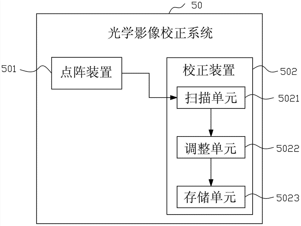
[0016] Such as image 3 As shown, the optical image correction system 50 is mainly applicable to the AOI machine to correct the image deformation problem in the AOI machine. The optical image correction system 50 mainly includes a dot matrix device 501 and a correction device 502 .

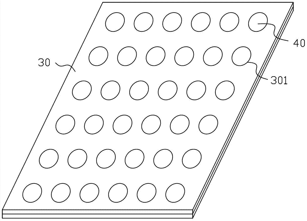
[0017] Among them, such as figure 2 As sh...


PUM


Abstract

The invention provides an optical image correction system which is mainly used for correcting an AOI drilling crew. The optical image correction system mainly comprises a dot matrix device and a correction device. The dot matrix device comprises a bottom plate and a dot matrix plate arranged on the bottom plate, and the dot matrix plate is provided with multiple rows of windows distributed in a dot matrix mode. The correction device mainly comprises a scanning unit, an adjusting unit and a storing unit, wherein the scanning unit is used for scanning the image of the dot matrix plate on the dot matrix device, the adjusting device is used for comparing the scanned image of the dot matrix plate and the windows of the dot matrix plate and updating and adjusting the position of an original point in the window at the lowermost right corner so that the windows of the dot matrix plate and the scanned image of the dot matrix plate can be overlapped, the storing unit is used for storing the updated position of the original point, and thus the correction process is completed. According to the optical image correction system, by means of correction, the real condition is presented in photos shot by the AOI drilling crew, the coordinates of an element model can be exactly matched with the actual element position, the purpose of correcting image deformation is achieved, and the problem that tools for correction are not available previously, the image deformation issue is generated, and using cannot be achieved is solved.

Description

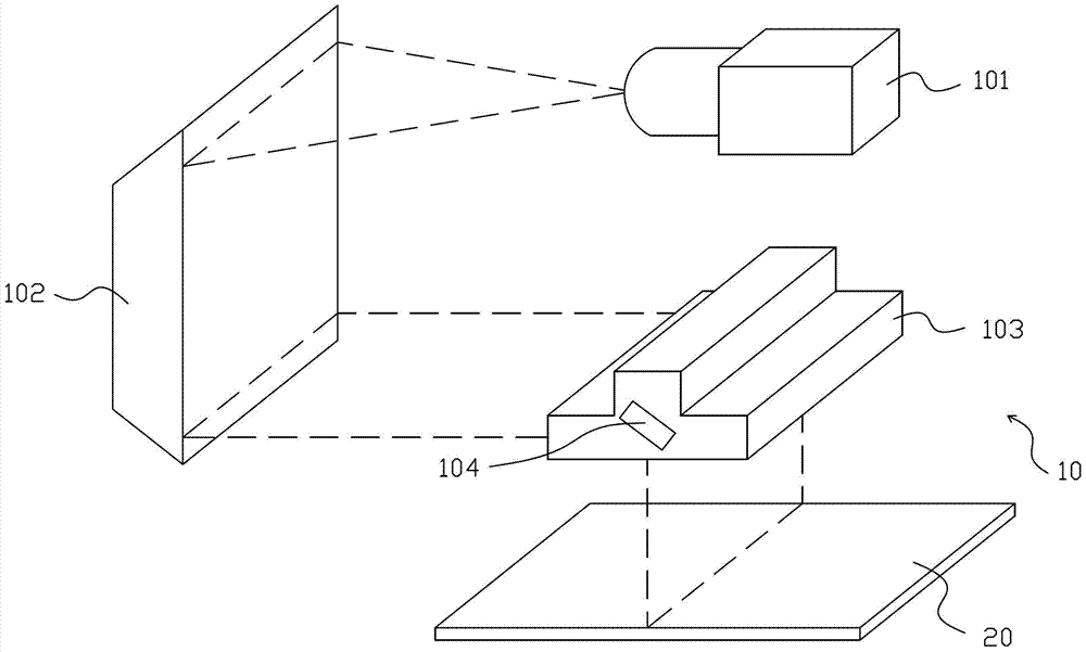
technical field [0001] The invention relates to an image correction device, in particular to an optical image correction system. Background technique [0002] At present, during the test, if the image of the AOI machine used is blurred, it will seriously affect the test, which will cause the machine to report an error during the power-on self-test, making it unusable. [0003] Such as figure 1 As shown, the working principle of the AOI machine is as follows. The SAKI machine 10 mainly includes a linear camera 101, a reflection unit 102, a light source unit 103, and a prism 104 arranged in the light source unit 103. The light emitted by the light source unit 103 is printed After the circuit board 20 passes through the prism 104, the reflection unit 102, and the linear camera 101 in sequence, the image can be obtained after refraction. Since the camera image has multiple refractions, if the image is formed without correction, the image will be distorted. If necessary If it i...

Claims


Application Information

Patent Timeline
Patent Type & Authority Patents(China)
IPC IPC(8): G06K9/32G06F11/22
CPCG06T7/80
Inventor 王振兵
Owner MITAC COMP (SHUN DE) LTD
Learn More