
City comprehensive pipe gallery

An integrated pipe gallery and city technology, which is applied in the sewer pipeline system, water conservancy project, waterway system, etc., can solve the problems of restricting the promotion and application of the integrated pipe gallery, large civil construction volume of the integrated pipe gallery, and restricting the use of the integrated pipe gallery. The effect of reducing the width and space of the road surface, reducing the size and capital investment, and simplifying the structure

Active Publication Date: 2015-01-21
沈晓铃
View PDF5 Cites 11 Cited by
  • Summary
  • Abstract
  • Description
  • Claims
  • Application Information

AI Technical Summary

Problems solved by technology

However, based on the needs of management, maintenance and maintenance, it is generally necessary to set up a channel for maintenance. According to the requirements of the specification, the width of the channel should not be less than 0.7~1.0 meters, which results in a large civil construction volume and high cost for the integrated pipe gallery. It also limits the popularization and application of integrated pipe gallery
In addition, in order to collect rainwater on the road surface, it is necessary to set up water collection facilities such as rainwater gutters or grates, which are installed independently outside the comprehensive pipe gallery. This requires that the municipal roads need to be wide enough to place these pipes and facilities, which also limits the comprehensive pipe gallery. Use of areas with insufficient pavement width

Method used


Image

  • City comprehensive pipe gallery
  • City comprehensive pipe gallery
  • City comprehensive pipe gallery

Examples


Embodiment Construction

[0016] The present invention will be further described below in conjunction with the accompanying drawings.

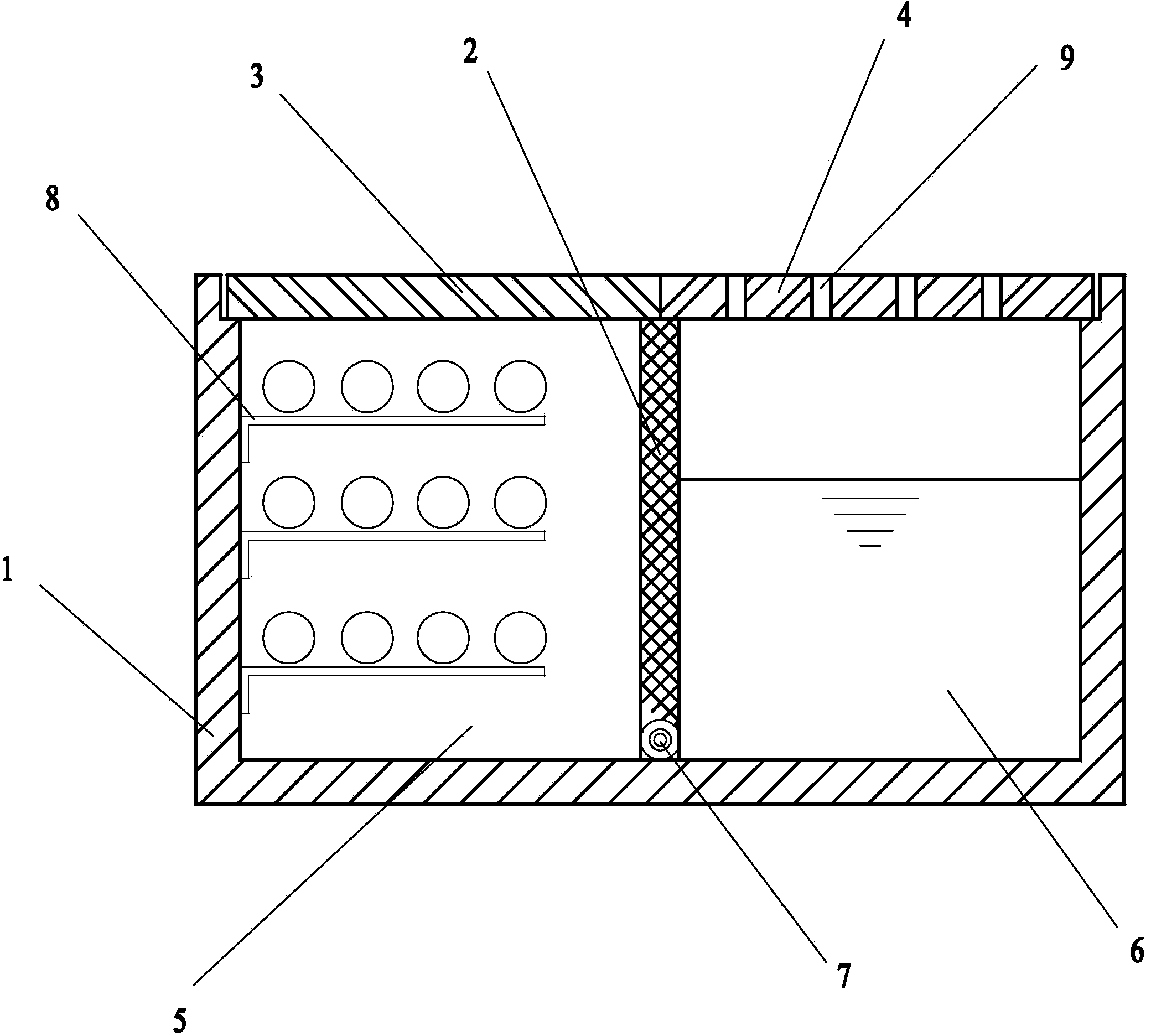
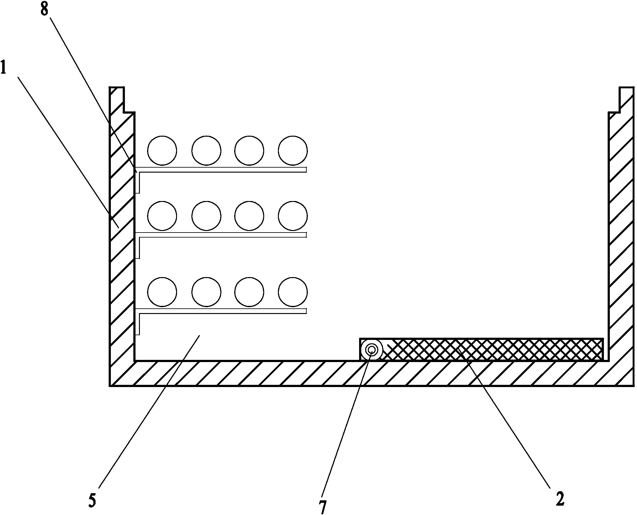
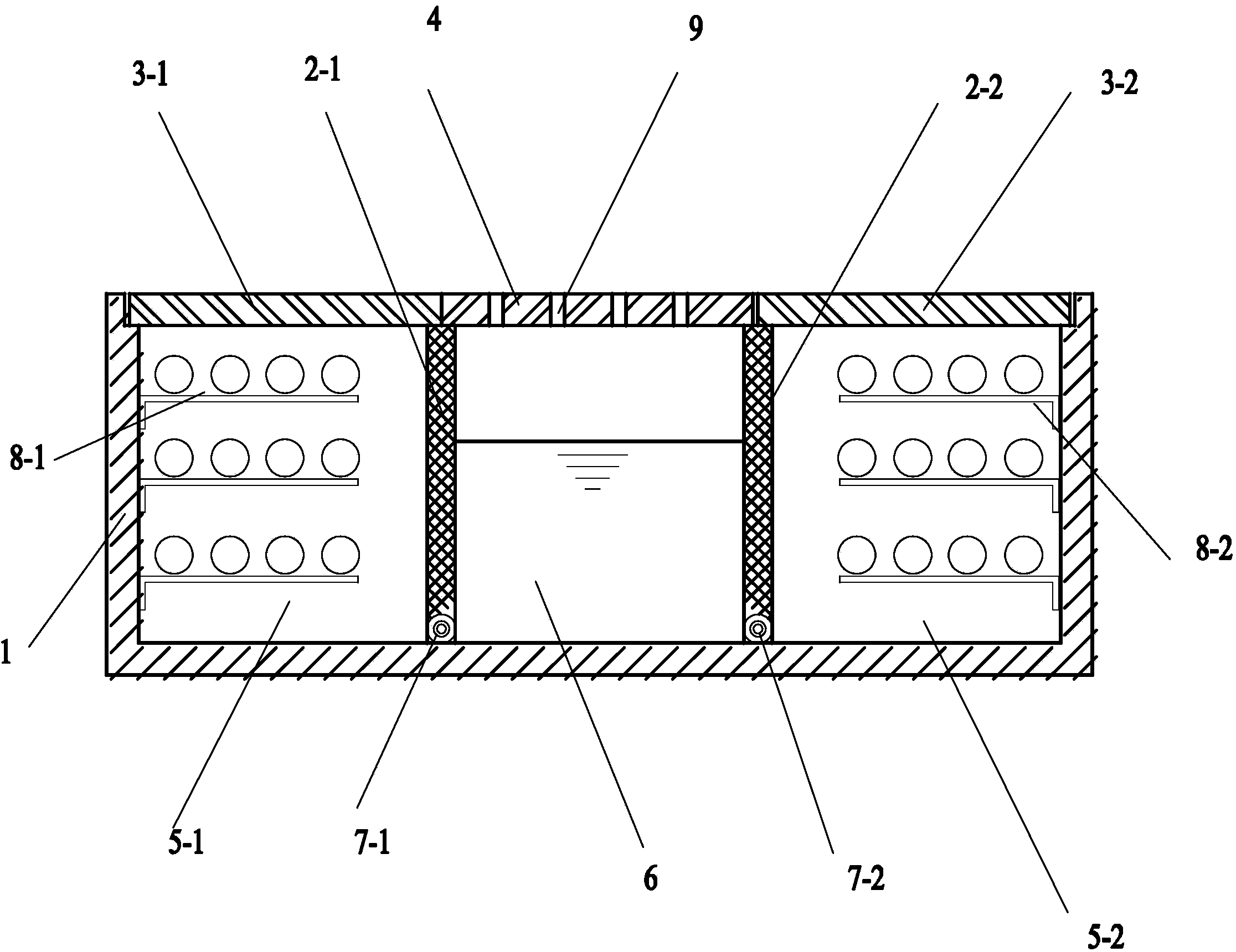
[0017] The design principle of the present invention is as follows: the main body of the corridor is divided into a pipe ditch and a drainage channel by using a middle partition, and various municipal pipes such as electric power, communication, water supply, and reclaimed water can be placed in the pipe ditch according to the requirements of the pipe arrangement. The upper cover plate is sealed; the cover plate above the drainage channel is provided with drain holes. When it rains, the rainwater enters the drainage channel through the drain hole and is quickly discharged. The drainage channel is isolated from the pipe groove by the middle partition to prevent rainwater from entering the pipe groove in the drainage channel. Interfering with or polluting other municipal pipelines in the pipe trench; when maintenance is required, open the cover and turn over the middle pa...


PUM


Abstract

The invention relates to a city comprehensive pipe gallery, and belongs to the technical field of public facilities. The city comprehensive pipe gallery comprises a gallery body. At least one middle separating plate is arranged inside the gallery body, the middle separating plate divides the gallery body into a pipe ditch portion and a drainage channel, the pipe ditch portion is used for containing municipal pipelines, a pipeline covering plate and a drainage covering plate are arranged at the upper portion of the pipe ditch portion and the upper portion of the drainage channel respectively, a plurality of drain holes are formed in the drainage covering plate, the lower portion of the middle separating plate is connected with the bottom surface of the gallery body through an overturning pin shaft, and a plurality of supports used for supporting the pipelines are arranged in the pipe ditch portion. The city comprehensive pipe gallery is simple in structure, is compact in design, can reduce the needed width of a road and needed space, and reduces the size and investment.

Description

technical field [0001] The invention relates to an urban comprehensive pipe gallery used in municipal construction, and belongs to the technical field of municipal facilities. Background technique [0002] Urban comprehensive pipe corridor, also known as common ditch, comprehensive pipe ditch, is to build an underground corridor under the municipal road, including various municipal pipelines such as electricity, communication, heat, water supply and drainage, and set up special maintenance Inlets, feeding ports and other facilities, unified construction management, eliminating the need for independent structures and earthwork excavation of the pipeline itself, can effectively and intensively use space resources. However, based on the needs of management, maintenance and maintenance, it is generally necessary to set a channel for maintenance. According to the requirements of the specification, the width of the channel should not be less than 0.7~1.0 meters, which results i...

Claims


Application Information

Patent Timeline
Patent Type & Authority Applications(China)
IPC IPC(8): E02D29/045E03F5/00
CPCE02D29/045E02D2200/1607E02D2200/1628E03F3/04
Inventor 沈晓铃王泽阳朱沙
Owner 沈晓铃
Learn More