
Laser ranging beam-splitting system

一种激光测距、屋脊的技术,应用在无线电波测量系统、测量距离、光学等方向,能够解决光分束器结构复杂、安装调试难度大、稳定性不高等问题,达到测量范围广、易于调试、结构简单紧凑的效果

Active Publication Date: 2015-01-21
LANHAI PHOTOELECTRICITY TECH CO LTD
View PDF7 Cites 22 Cited by
  • Summary
  • Abstract
  • Description
  • Claims
  • Application Information

AI Technical Summary

Problems solved by technology

[0003] The purpose of the present invention is to overcome the shortcomings of the existing optical beam splitter of the laser rangefinder, such as complex structure, large volume, difficult installation and debugging, and low stability, and provide a simple and compact structure, small volume, easy installation and debugging, and high stability. A laser ranging beam splitting system with high precision and high measurement accuracy

Method used


Image

  • Laser ranging beam-splitting system
  • Laser ranging beam-splitting system
  • Laser ranging beam-splitting system

Examples


example 1

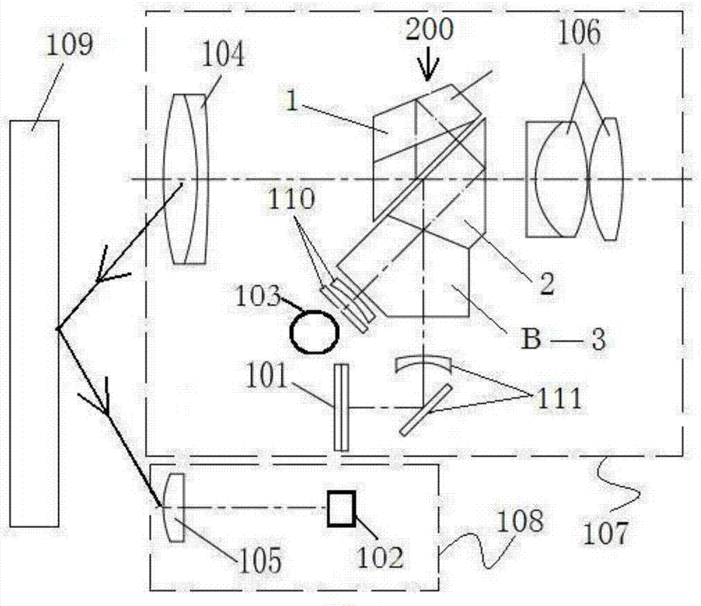
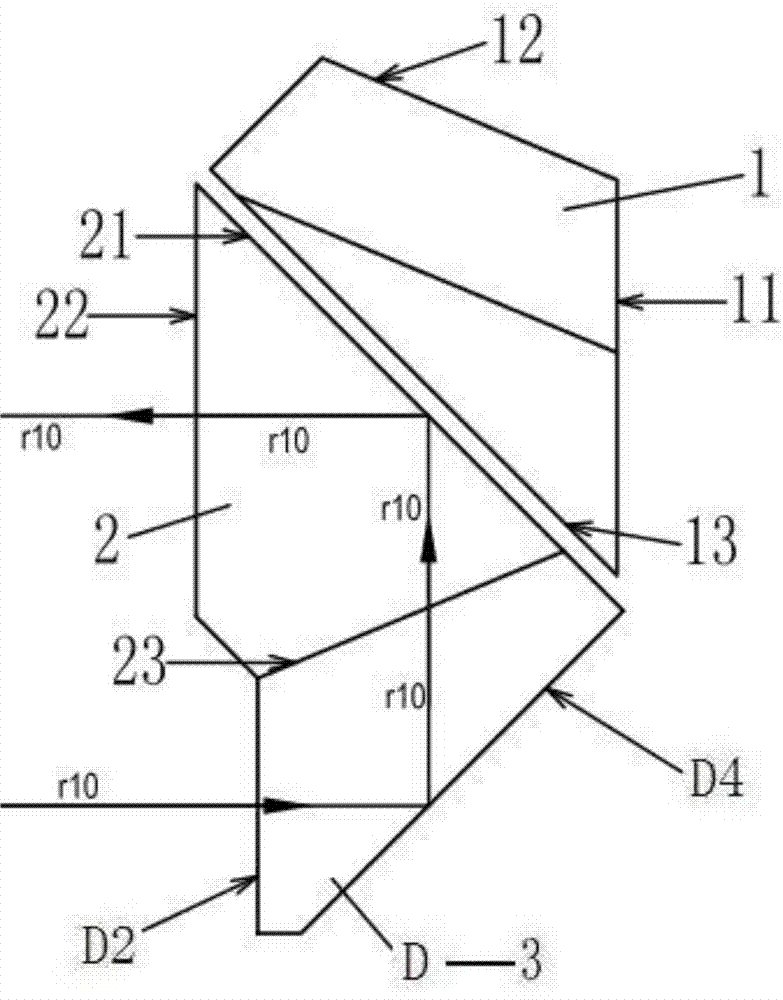
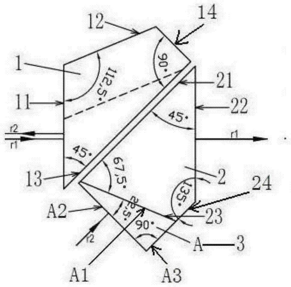
[0041] Example 1: A laser ranging beam splitting system, see figure 1 , figure 2 , image 3 As shown, it includes: a roof half pentaprism (1), an isosceles prism (2) and a compensation prism (3), and the compensation prism is No. 1 compensation prism (A).

[0042] The ridge semi-pentaprism comprises: the ridge transceiving surface (11), the ridge external reflection surface (12), the ridge internal reflection surface (13) and the ridge top surface (14), and the two ends of the ridge transmission and reception surface are connected with one end of the ridge external reflection surface respectively. It intersects with one end of the internal reflective surface of the ridge, and the two ends of the top surface of the ridge intersect with the other end of the external reflective surface of the ridge and the other end of the internal reflective surface of the ridge, and the angle between the external reflective surface of the ridge and the transceiver surface of the ridge is 112....

example 2

[0050] Example 2: see Figure 5 As shown, when installing, Figure 5 and Figure 4 The difference is that the Figure 4 The receiver (102) in the No. 1 transceiver system (107) has been changed into a transmitter (103), and the Figure 4 The transmitter (103) in the No. 2 transceiver system (108) has been replaced by a receiver (102), Figure 5 other structures of Figure 4structure is exactly the same. In Example 2, when in use, the No. 1 transceiver system (107) emits laser light, and then the No. 2 transceiver system (108) receives the laser light. see figure 1 , figure 2 , image 3 As shown, the propagation direction of the laser beam in Example 2 is just opposite to that of the laser beam in Example 1. The working principle of Example 2 is the same as that of Example 1. Please refer to Example 1 for the specific installation process and working process.

[0051] Example 3: see Figure 10 as shown, Figure 10 and Figure 4 The difference is that: one is to put...


PUM


Abstract

The invention, which relates to the technical field of light beam separation, discloses a laser ranging beam-splitting system having advantages of simple and compact structure, diversified light splitting types, wide measurement range, and high stability and measurement precision. The system comprises a ridge semi-pentagonal prism, an isosceles prism, and a compensating prism. Because of the difference of the compensating prism, four kinds of light splitting combination units can be provided. Light with a certain wavelength enters from one side of the ridge semi-pentagonal prism; after reflection inside the prism at multiple times, the light is emitted and enters the isosceles prism; and likewise, after reflection at multiple times, the light is emitted at the direction consistent to the incident optical axis. Light with another wavelength enters from one side of the compensating prism and is emitted from one side of the ridge semi-pentagonal prism or one side of the isosceles prism. Because different light splitting ways are caused by different prism placing positions and data display LCD positions, various ranging optical systems can be generated when the laser range finder uses different light splitting combination units.

Description

technical field [0001] The invention relates to the technical field of beam splitting, in particular to a laser ranging beam splitting system. Background technique [0002] At present, the optical beam splitter of the laser rangefinder has a complex structure and a large volume, which is difficult to install and debug, and it is not easy to control the path of beam separation and transmission, and the stability is not high. Contents of the invention [0003] The purpose of the present invention is to overcome the shortcomings of the existing optical beam splitter of the laser rangefinder, such as complex structure, large volume, difficult installation and debugging, and low stability, and provide a simple and compact structure, small volume, easy installation and debugging, and high stability. It is a laser ranging beam splitting system with high precision and high measurement accuracy. [0004] In order to achieve the above object, the present invention adopts the follow...

Claims


Application Information

Patent Timeline
Patent Type & Authority Applications(China)
IPC IPC(8): G01S7/481
CPCG02B27/145G01C3/02G02B27/126G01S7/4811
Inventor 左罗钱向伟
Owner LANHAI PHOTOELECTRICITY TECH CO LTD
Learn More