Over-roof prevention installation structure between photoelectric cabin and motion carrier

A technology of motion carrier and installation structure, applied in the direction of non-electric variable control, instrument, position/direction control, etc., can solve the problem of photoelectric stabilized platform over the top

Inactive Publication Date: 2015-01-21
LUOYANG INST OF ELECTRO OPTICAL EQUIP OF AVIC
View PDF6 Cites 0 Cited by
  • Summary
  • Abstract
  • Description
  • Claims
  • Application Information

AI Technical Summary

Problems solved by technology

[0008] The purpose of the present invention is to provide an anti-overhead installation structure between the photoelectric cabin body and the moving carrier, so as to solve the overtop problem of the photoelectric stabilized platform

Method used


Image

  • Over-roof prevention installation structure between photoelectric cabin and motion carrier
  • Over-roof prevention installation structure between photoelectric cabin and motion carrier
  • Over-roof prevention installation structure between photoelectric cabin and motion carrier

Examples


Embodiment Construction

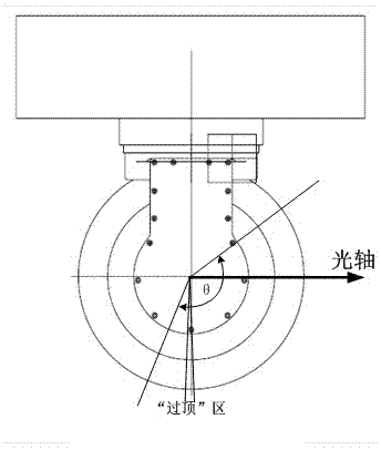
[0017] An embodiment of the anti-overhead installation structure between the photoelectric cabin body and the moving carrier, such as Figure 4 As shown, the anti-overhead installation structure between the photoelectric cabin body and the moving carrier includes a photoelectric cabin body 11 and a moving carrier 12 .

[0018] In this embodiment, the bottom of the moving carrier 12 is provided with an inclined surface that gradually slopes upward from the front to the rear relative to the horizontal plane, and the inclined surface is used for installing the photoelectric cabin body 11 .

[0019] The photoelectric cabin body 11 has an optical axis. In the present embodiment, the photoelectric cabin body 11 is installed vertically on the inclined surface of the moving carrier 12, thus making it tilt backward and forming an angle with the vertical plane. The included angle makes the overhead area of ​​the photoelectric cabin body 12 avoided outside the working angle range of the ...


PUM


Abstract

The invention relates to the technical field of airborne photoelectric, and especially relates to an over-roof prevention installation structure between a photoelectric cabin and a motion carrier, comprising a photoelectric cabin and a motion carrier. The photoelectric cabin is provided with an optical axis. One end of the photoelectric cabin is fixedly assembled on the motion carrier, the other end gradually inclines forward or backward, and an inclination angle used for making the over-roof region of the photoelectric cabin deviate from the working angle range of the optical axis is formed between the other end and a vertical plane. When the photoelectric cabin passes right above an object, the situation in which the optical axis is vertically downward can be avoided, so that the optical axis is prevented from entering the over-roof region of the photoelectric cabin. By adopting the over-roof prevention installation structure between a photoelectric cabin and a motion carrier, the problem that a photoelectric stabilized platform is over-roof is solved without the need to increase any parts.

Description

technical field [0001] The invention relates to the field of airborne photoelectric technology, in particular to an anti-overhead installation structure between a photoelectric cabin body and a moving carrier. Background technique [0002] Some optoelectronic products have the functions of navigating, quickly capturing, and tracking targets. They are often suspended on moving carriers (such as aircraft, ships, etc.) and used for high-resolution ground observation, aerial photography and mapping, and power line inspection. and other fields. These optoelectronic products all include an optoelectronic cabin with a photoelectric sensor device installed outside and an optoelectronic stabilized platform located in the optoelectronic stabilized cabin. [0003] The structural shapes of the above products usually have two types: spherical and cylindrical, among which spherical products are the most widely used. The core component of the spherical product is the photoelectric stabil...

Claims


Application Information

Patent Timeline
Patent Type & Authority Applications(China)
IPC IPC(8): G05D3/00
Inventor 牛学东马晓鹏
Owner LUOYANG INST OF ELECTRO OPTICAL EQUIP OF AVIC
Why Eureka
Try Eureka