
Surface temperature detection device for stirring friction welding leader region

A surface temperature and friction stir technology, which is applied in the direction of measuring devices, thermometers, welding equipment, etc., can solve the problems of lack of dynamic detection of friction stir welding zone, difficulty in measuring the temperature of stirring zone, and difficult detection of dynamic temperature change in welding zone, etc., to achieve structural Simplicity, strong practicality, and high device reliability

Inactive Publication Date: 2015-01-28
JIANGSU UNIV OF SCI & TECH
View PDF6 Cites 17 Cited by
  • Summary
  • Abstract
  • Description
  • Claims
  • Application Information

AI Technical Summary

Problems solved by technology

However, during the friction stir welding process, the friction stir head moves and the position of the welding zone changes dynamically, so it is difficult to detect the dynamic change of the temperature of the welding zone by using the above-mentioned fixed point temperature measurement method; in addition, due to the influence of the friction stir head in the welding zone , it is difficult to measure the temperature in the stirring area, so measuring the dynamic change of temperature in the adjacent area of ​​welding is also an effective way to indirectly analyze the temperature of the welding area
[0004] However, it can be seen from the above analysis that there is currently a lack of a method and device for dynamically detecting the temperature of the friction stir welding zone or the adjacent area, so it is of great practical significance to propose a related detection device

Method used


Image

  • Surface temperature detection device for stirring friction welding leader region
  • Surface temperature detection device for stirring friction welding leader region
  • Surface temperature detection device for stirring friction welding leader region

Examples


Embodiment Construction

[0028] The present invention will be further described below in conjunction with the accompanying drawings.

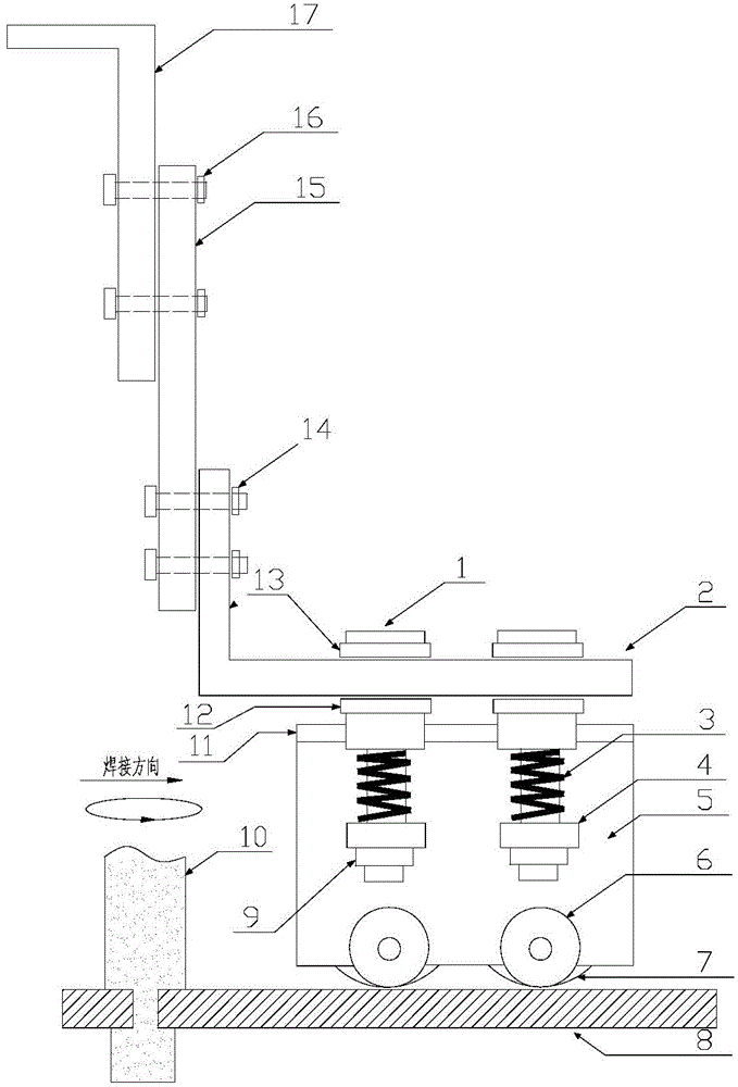
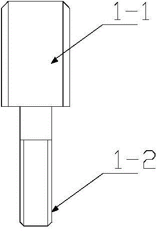
[0029] like Figure 1 to Figure 8 As shown, a friction stir welding leading zone surface temperature detection device of the present invention includes a compression spring thermocouple 7 for detecting the surface temperature of the leading zone, a trolley 5 that drives the compression spring thermocouple 7 to move, and an adjustment device connected to the trolley 5 device, the compression spring thermocouple 7 is connected to the trolley 5 through four sets of thermocouple kits, the side of the trolley 5 is provided with four trolley bosses 4, the trolley boss 4 is connected to the adjustment device through a spring adjustment structure, and the bottom of the trolley 5 is equipped with rollers 6.

[0030] In the present invention, the thermocouple kit includes a hollow step-shaped thermocouple mounting rod 18-4, a buffer spring 18-3, a pressure sensor 18-2 and a cov...


PUM


Abstract

The invention discloses a surface temperature detection device for a stirring friction welding leader region. The surface temperature detection device comprises a compression spring type thermocouple, a trolley and an adjusting device, wherein the compression spring type thermocouple is used for detecting the surface temperature of the leader region, the trolley is used for driving the compression spring type thermocouple to move, and the adjusting device is connected with the trolley; the compression spring type thermocouple is connected with the trolley through a thermocouple cover piece; trolley bosses are arranged on the side face of the trolley, and are connected with the adjusting device through a spring adjusting structure; rollers are arranged at the bottom of the trolley. According to the surface temperature detection device for the stirring friction welding leader region, disclosed by the invention, the surface of the welding leader region can be detected, free adjustment of welding positions in longitudinal, transverse and vertical directions is realized, and the device is simple in whole structure, low in cost and high in practicability; moreover, the device is easy to implement and convenient to assemble, and has practical significance on automatic detection of stirring friction welding.

Description

technical field [0001] The invention relates to the field of metal material processing, in particular to a surface temperature detection device for a leading zone of friction stir welding. Background technique [0002] In the friction stir welding process, the temperature of the welding zone has a great influence on the welding surface shape and welding quality. When the temperature in the welding zone is low, the plasticity of the material is insufficient, resulting in insufficient material flow, and groove defects will appear; when the temperature in the welding zone is too high, the material softens severely, the viscosity increases, and the high-temperature material sticks to the stirring head. It is difficult for the material to flow to the rear of the stirring head, which directly leads to poor surface formation and more welding defects. In this case, the double-shouldered friction stirring head may even cause the stirring needle to break. Therefore, in the context of...

Claims


Application Information

Patent Timeline
Patent Type & Authority Applications(China)
IPC IPC(8): B23K20/12B23K20/26G01K7/02
CPCB23K20/1235
Inventor 陈书锦王宇方伟强李浩薛俊荣
Owner JIANGSU UNIV OF SCI & TECH
Learn More