Inflow control device

A technology of inflow control and diversion mechanism, which is applied in the direction of production fluid, wellbore/well components, earthwork drilling and production, etc. It can solve the problems of unbalanced flow and negative impact on production efficiency in horizontal wells, and achieve the effect of improving service life

Active Publication Date: 2015-01-28
PETROCHINA CO LTD
View PDF5 Cites 12 Cited by
  • Summary
  • Abstract
  • Description
  • Claims
  • Application Information

AI Technical Summary

Problems solved by technology

The state of the reservoir is dynamically changing, and the fluid viscosity, density, and velocity will change with time, so the fixed ICD cannot adapt to these dynamic changes, resulting in flow imbalance in horizontal wells, which in turn affects production efficiency result in negative effect

Method used


Image

  • Inflow control device
  • Inflow control device
  • Inflow control device

Examples


Embodiment Construction

[0025] The details of the present invention can be understood more clearly with reference to the accompanying drawings and the description of specific embodiments of the present invention. However, the specific embodiments of the present invention described here are only for the purpose of explaining the present invention, and should not be construed as limiting the present invention in any way. Under the teaching of the present invention, the skilled person can conceive any possible modification based on the present invention, and these should be regarded as belonging to the scope of the present invention.

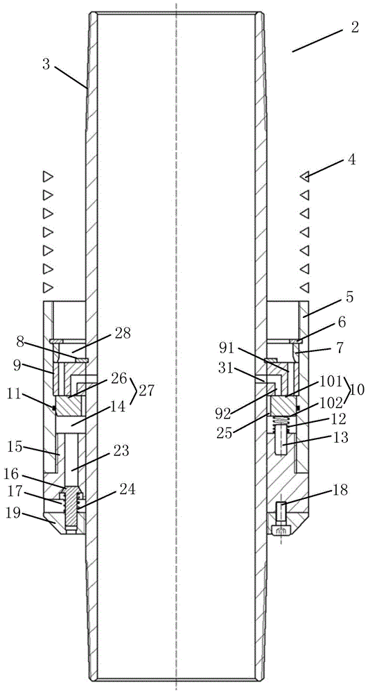
[0026] figure 1 It is a structural schematic diagram of the inflow control device 2 in the initial state of the present invention, such as figure 1 shown. An inflow control device 2 proposed by the present invention includes: a central tube 3, which is in the shape of a hollow circular tube, and a through hole 31 is opened on the tube wall; a casing 5, which is sleeved ...


PUM


Abstract

The invention discloses an inflow control device. The inflow control device comprises a central pipe, a shell which sleeves the external part of the central pipe, a flow guide mechanism, an adjusting part, a limiting mechanism and, a locking disc, wherein the pipe wall of the central pipe is provided with through holes; the flow guide mechanism is located in n annular space and is used for dividing the annular space into a first space and a second space, and the internal part of the flow guide mechanism is provided with a first passage used for communicating the first space with the second space and a second passage used for communicating the second space with the through hole; the adjusting part can slide along the axial direction in the second space and divides the second space into a first chamber and a second chamber, and the adjusting part and the central pipe form a flowing passage used for communicating the first chamber with the second chamber; the limiting mechanism can retain the adjusting part; the locking disc is connected to the lower end of the shell. The inflow control device can realize automatic response to inflow fluid viscosity, so as to adjust the inflow flow rate of the fluid, realize the effect of balancing the flowing section of a horizontal well and achieve the goals of yield stabilization, yield increase and water control.

Description

technical field [0001] The invention relates to the technical field of horizontal well water control in oil fields, in particular to an inflow control device. Background technique [0002] Advanced drilling techniques have made horizontal wells the primary design type for developing reservoirs, especially unconventional reservoirs. Horizontal wells can increase the drainage area of ​​production layers, and are an important technical means to improve oil recovery efficiency and increase recoverable reserves. However, horizontal wells also suffer from a serious problem - non-uniform flow profiles, which are usually caused by non-uniform pressure differentials along the horizontal section of the reservoir and uneven distribution of pressure and permeability across individual formations. Uneven flow profiles can lead to premature moisture breakthrough, screen plugging, and erosion of sand wells, which can severely reduce well life and productivity. [0003] In order to elimina...

Claims


Application Information

Patent Timeline
Patent Type & Authority Applications(China)
IPC IPC(8): E21B43/12E21B21/10
CPCE21B43/12
Inventor 刘合裴晓含郑立臣俞佳庆高扬
Owner PETROCHINA CO LTD
Why Eureka
Try Eureka