A swash plate drum cable laying machine

A swash plate type, cable laying machine technology, applied in cable laying equipment and other directions, can solve the problems of inability to disassemble, transport and install, complex hydraulic pipelines, valve parts, large structure and external dimensions of the reel cable laying machine, etc. Achieve the effect of ensuring cable safety, easy transportation, and easy modular installation

Active Publication Date: 2019-01-22
上海凯波水下工程有限公司
View PDF5 Cites 0 Cited by
  • Summary
  • Abstract
  • Description
  • Claims
  • Application Information

AI Technical Summary

Problems solved by technology

However, the control method using hydraulic drive to rotate the reel is realized by adjusting the opening of the valve. It is an analog control, and it is difficult to achieve automatic response and precise control.
[0005] Due to the large structure and dimensions of the reel cable laying machine, and the existence of supporting facilities such as hydraulic stations, various hydraulic pipelines and valves are even more intricate.
Therefore, the drum turbine driven by this type is limited to being permanently fixed on a ship, and cannot be disassembled, transported and installed in a modular manner

Method used


Image

  • A swash plate drum cable laying machine
  • A swash plate drum cable laying machine
  • A swash plate drum cable laying machine

Examples


Embodiment approach

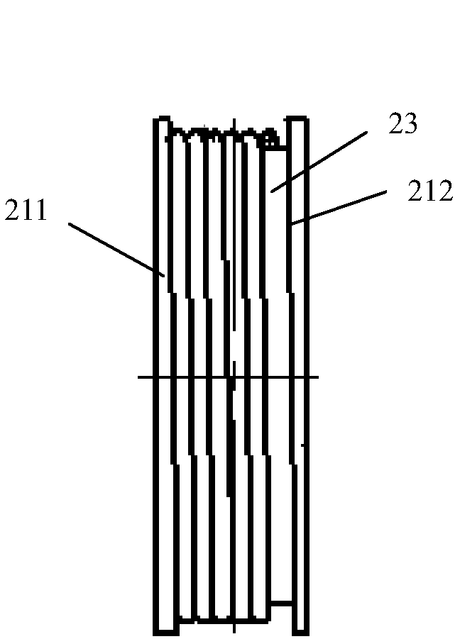
[0046] In further embodiments of the present invention, please continue to refer to Figure 2c As shown, both the swash plate 211 and the swash plate 212 have annular inner walls, and the left and right ends of the reel 23 are respectively arranged inside the inner annular walls of the swash plate 211 and the swash plate 212, the annular inner wall of the swash plate 211 and the annular inner wall of the swash plate 212 There is a gap between the inner wall and the cylindrical outer wall of the reel 23, and the gap is not more than 3mm, which effectively ensures that the cable will not be squeezed into the gap and damaged, especially when the reel is running at high speed, the cable is prevented from being damaged by asphalt. The silk-wrapped case is damaged.

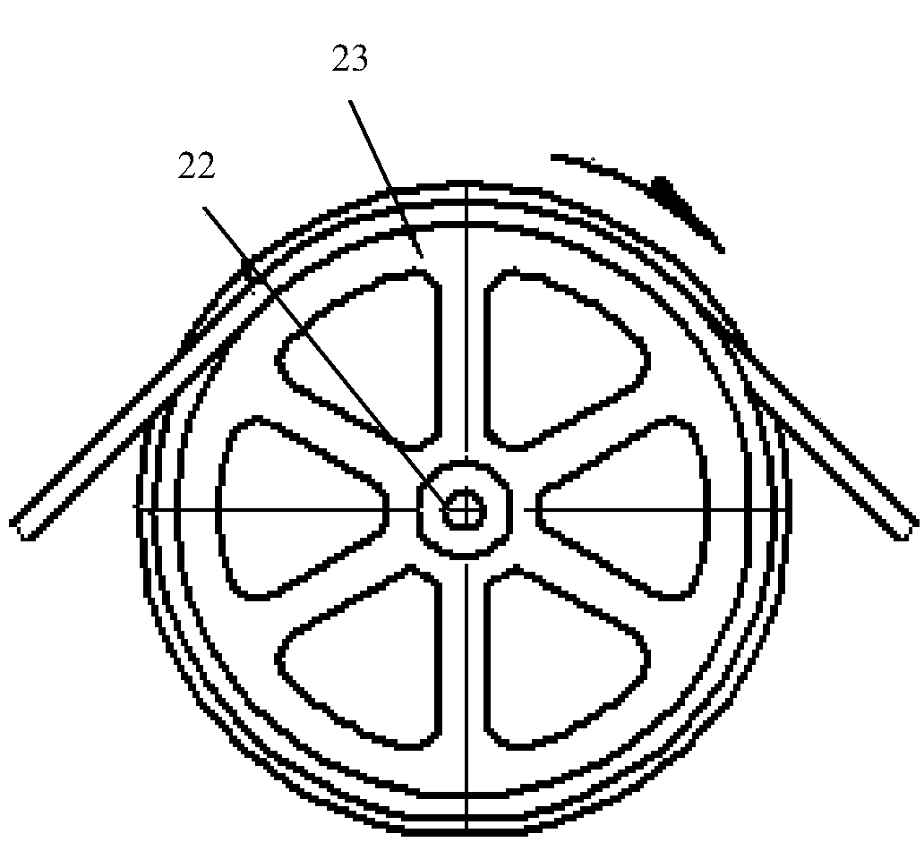
[0047] In a further embodiment of the present invention, the spokes 243 of the swash plate 211 and the swash plate 212 are in a circular array.

[0048] In a further embodiment of the present invention, the inclination...


PUM


Abstract

The invention discloses a reel cable-laying machine of an inclined disc type, and the reel cable-laying machine comprises an inclined disc type drum wheel machine which is disposed on a laying ship; and a combined tyre machine which is disposed at a lower work position of the inclined disc type drum wheel machine. The inclined disc type drum wheel machine is driven to operate through three motors. A motor control cabinet comprises a PLC, three frequency converters, and three braking resistors. The PLC is connected with the three frequency converters, and each frequency converter is connected with one braking resistor and one motor. An industrial computer is connected with the PLC, and the PLC is controlled through the industrial computer. Sensors are used for detecting the rotating speeds, torques and cable laying lengths of three motors, and are connected with the PLC. The reel cable-laying machine also comprises a GPS navigator which is connected with the industrial computer. The reel cable-laying machine avoids the manual operation of a cable sorting knife of a cable-laying machine, achieves a purpose of automatically sorting the marine cables on a reel, and guarantees the safety of the cables. The reel cable-laying machine employs the technologies of frequency conversion and computer control, achieves the automatic response and precise control in the construction process of a deep seat cable, employs a mode of electric dragging, and facilitates the conveying and modular installation.

Description

technical field [0001] The invention relates to the technical field of cable laying machines, in particular to a swash plate type drum cable laying machine. Background technique [0002] At present, the method of forced combing of submarine cables by the splitting knife process used by drum cable laying machines is extremely unsafe: when laying or salvaging deep-sea submarine cables, in order to obtain sufficient traction or braking force for submarine cables, it is usually Several turns are helically wound on a cylindrical reel with a diameter of about 3m. During salvage or laying operations, as the drum rotates, the submarine cable is continuously laid out, and the spirally wound cable will also move along the axial direction of the drum. When it is blocked by the wall plate on one side of the drum , The cables will overlap and cross here, which will cause the construction to be suspended, and serious quality accidents will occur. [0003] In order to prevent this situat...

Claims


Application Information

Patent Timeline
Patent Type & Authority Patents(China)
IPC IPC(8): H02G1/10
CPCH02G1/10
Inventor 曹火江李林森
Owner 上海凯波水下工程有限公司
Why Eureka
Try Eureka