
Engine water pump

A technology for engines and water pumps, which is applied in the cooling of engine components, machines/engines, and engines. It can solve problems such as poor engine cooling, decreased coolant flow, and decreased pumping capacity of water pumps, so as to avoid poor cooling.

Inactive Publication Date: 2015-01-28
GUANGXI YUCHAI MASCH CO LTD
View PDF14 Cites 0 Cited by
  • Summary
  • Abstract
  • Description
  • Claims
  • Application Information

AI Technical Summary

Problems solved by technology

[0003] Damage is difficult to predict due to uncontrollable engine water pump belt life
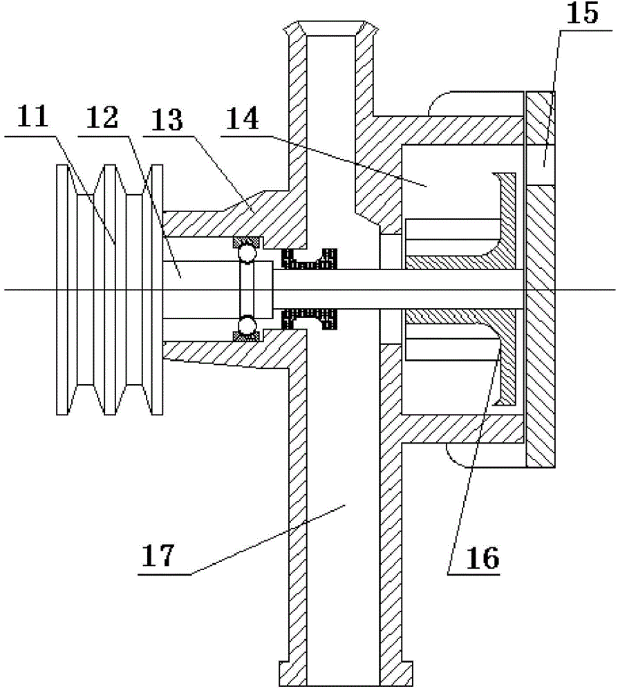
Once the tension of the water pump belt drops or is damaged or broken, the force driving the water pump pulley 11 will drop, and the water pump pulley will drop (or be zero) when the water pump pulley turns 11 speeds, causing the ability of the water pump to pump water to drop, which in turn will cause the flow rate of the coolant to drop (or is zero), causing the engine to fail due to poor cooling

Method used


Image

  • Engine water pump
  • Engine water pump
  • Engine water pump

Examples


Embodiment Construction

[0014] The specific embodiments of the present invention will be described in detail below in conjunction with the accompanying drawings, but it should be understood that the protection scope of the present invention is not limited by the specific embodiments.

[0015] Unless expressly stated otherwise, throughout the specification and claims, the term "comprise" or variations thereof such as "includes" or "includes" and the like will be understood to include the stated elements or constituents, and not Other elements or other components are not excluded.

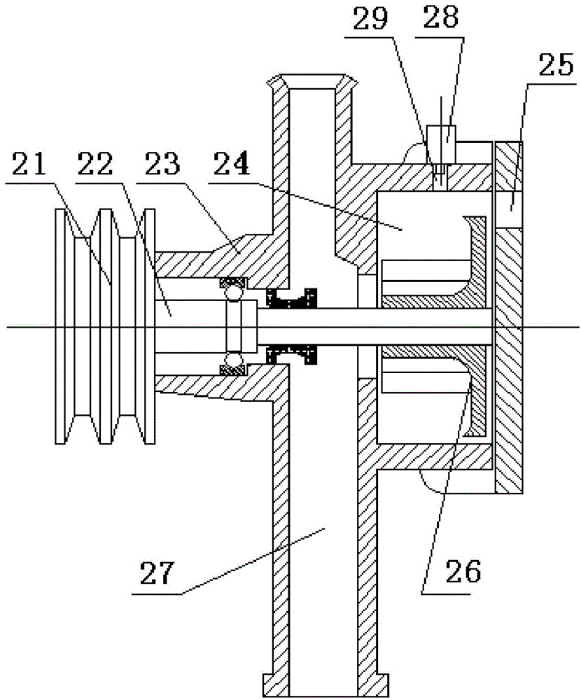
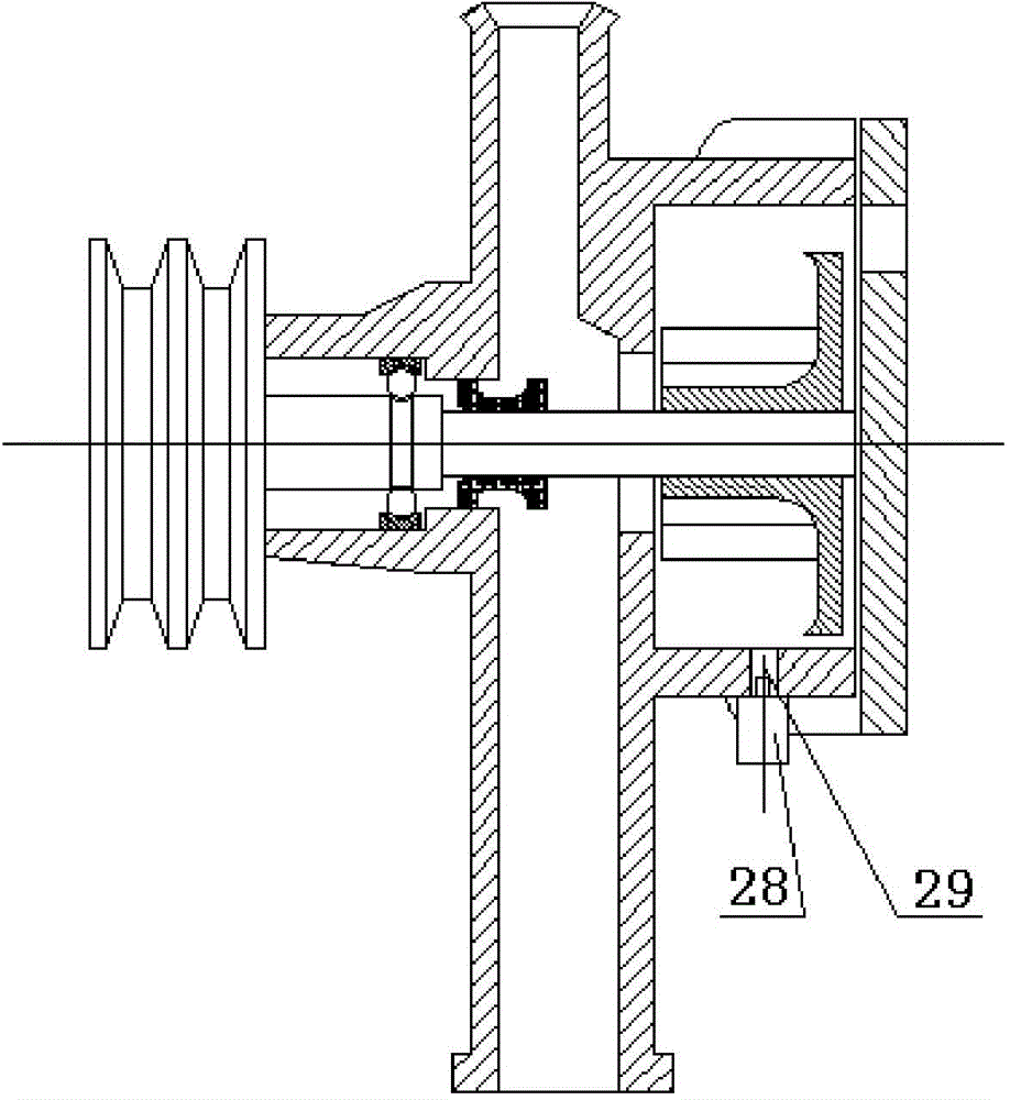
[0016] Such as Figure 2 to Figure 4 As shown, the specific structure of the engine water pump according to the specific embodiment of the present invention includes: a water pump body and a pressure sensor 28 for monitoring the water pump pressure at the water pump high pressure cavity of the water pump body, wherein the water pump body does not change the main structure of the original water pump and pump function. The ...


PUM


Abstract

The invention discloses an engine water pump. The engine water pump comprises a water pump body and a pressure sensor, wherein a water pump belt wheel and a water pump shaft are coaxially arranged; the water pump shaft is mounted in a water pump shell; the water pump shaft is driven by the water pump belt wheel to drive a rotary impeller to rotate to form a water pump high-pressure cavity in the water pump shell; a pressure sampling hole is formed in the water pump shell corresponding to the water pump high-pressure cavity; the pressure sensor is directly mounted on the pressure sampling hole or is connected with the pressure sampling hole by a pressure guide pipe and is used for sampling cooling liquid pressure in the water pump high-pressure cavity. According to the engine water pump, the pressure sensor for measuring pressure of a water pump is additionally arranged on the water pump high-pressure cavity on the basis of not changing an original main structure and a water pumping function of the water pump, and the pressure of the water pump high-pressure cavity is monitored in real time; a water pump flow and pressure have a corresponding relation so that the descending of the water pump can be found in time and necessary measures are adopted; a fault that the flow of the cooling liquid is decreased so that the cooling of an engine is not good is avoided.

Description

technical field [0001] The invention relates to the field of engines, in particular to an engine water pump. Background technique [0002] Typical belt-driven water pump configurations for existing engines, such as figure 1 As shown, the water pump pulley 11 is arranged coaxially with the water pump shaft 12 , and the water pump shaft 12 is installed in the water pump body 13 . Driven by the water pump pulley 11, the water pump shaft 12 rotates together, and the impeller 16 rotates, so that cooling water is sucked in from the water pump inlet 17, and produces high pressure in the water pump high-pressure chamber 14, and finally discharged from the water pump outlet 15. [0003] Because engine water pump belt life is uncontrollable, damage is difficult to predict. Once the tension of the water pump belt drops or is damaged or broken, the force driving the water pump pulley 11 will drop, and the water pump pulley will drop (or be zero) when the water pump pulley turns 11 spe...

Claims


Application Information

Patent Timeline
IPC IPC(8): F01P7/14F04D15/00
CPCF01P5/10F01P5/14F01P7/14F04D15/0077
Inventor 李欢周道林
Owner GUANGXI YUCHAI MASCH CO LTD
Learn More