Intelligent temperature control oil saving system

A technology of intelligent temperature control and electric control box, which is applied in the direction of heating/cooling equipment, air handling equipment, jet propulsion device, etc., which can solve the problems of difficult disassembly of the engine, high fuel consumption, and large fuel consumption, so as to achieve easy installation and the effect of dismantling and repairing

Active Publication Date: 2019-12-27
ANHUI ANKAI AUTOMOBILE
View PDF9 Cites 0 Cited by
  • Summary
  • Abstract
  • Description
  • Claims
  • Application Information

AI Technical Summary

Problems solved by technology

[0004] The purpose of the present invention is to provide an intelligent temperature control and fuel-saving system to solve the problem of high fuel consumption in the existing automobile temperature control system, and the engine fixing structure is relatively complicated, which needs to be fixed multiple times by bolts and nuts, otherwise the engine It is easy to slide when working; the existing engine needs to use bolts and nuts when it is fixed. After a long time of use, the thread is easily damaged, which makes it difficult to disassemble the engine, and the installation, disassembly and maintenance of the engine are more difficult; when the existing car needs to be refrigerated , because the hot air pipe and the cold air pipe share the same pipe and are not independent of each other. When cooling is avoided, the engine will be heated to the cold air pipe and cause the internal cold air to be heated, making the cooling effect poor. It is necessary to increase the power of the condenser, so that The problem of increased fuel consumption and high fuel consumption

Method used


Image

  • Intelligent temperature control oil saving system
  • Intelligent temperature control oil saving system
  • Intelligent temperature control oil saving system

Examples


Embodiment Construction

[0029] The technical solutions of the present invention will be clearly and completely described below in conjunction with the embodiments. Apparently, the described embodiments are only some of the embodiments of the present invention, not all of them. Based on the embodiments of the present invention, all other embodiments obtained by persons of ordinary skill in the art without creative efforts fall within the protection scope of the present invention.

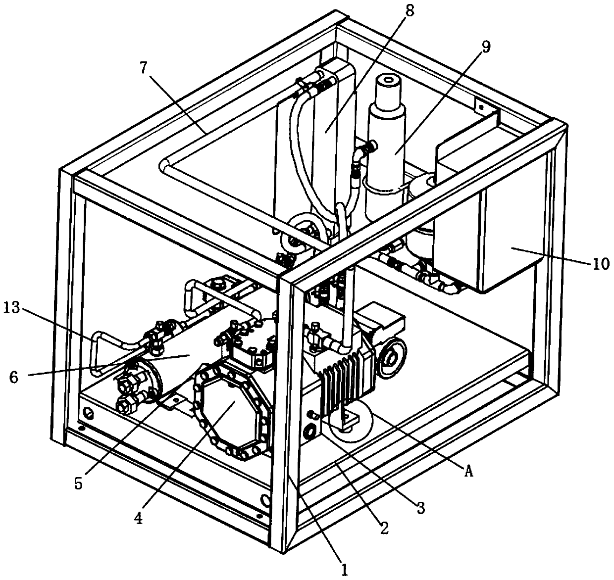
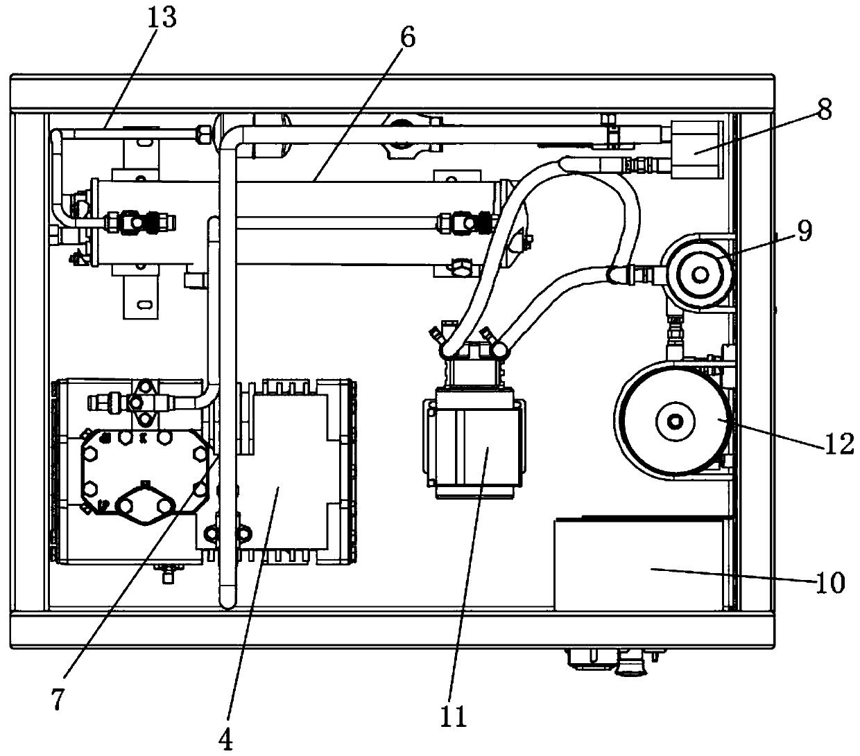
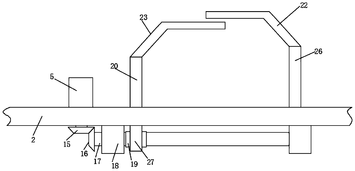
[0030] Such as Figure 1-5 As shown, an intelligent temperature control and fuel-saving system includes a fixed frame 1, a bottom plate 2 and a clamping device 3. The inside of the fixed frame 1 is provided with a bottom plate 2 near the bottom, and one end of the fixed frame 1 is installed on the side wall There is an electric control box 10, a filter 9 is arranged on the fixed frame 1 on one side of the electric control box 10, and an air collecting pipe 8 is arranged on one side of the filter 9, and the air collecting pi...


PUM


Abstract

The invention discloses an intelligent temperature control oil saving system. The system comprises a fixing frame, a bottom plate and a clamping device, the bottom plate is arranged at the position, close to the bottom, in the fixing frame, and an electric control box is arranged on the side wall of one end in the fixed frame. A filter is arranged on the fixing frame at one side of the electric control box, the output end of a motor drives a driving bevel gear to rotate, and the driving bevel gear drives a transmission bevel gear to rotate, so that a rotating shaft rotates between the two fixing blocks. The rotating shaft penetrates through a nut seat and is in threaded connection with the nut seat, so that a sliding block can be driven to slide and moves towards the direction of the fixing plate, and then a movable plate moves towards the fixing plate. An inserting plate is inserted into a notch, so that the distance between the movable plate and the fixing plate is further reduced, an engine is clamped and fixed without needing the bolts and nuts, the situation that the engine is difficult to detach due to the thread damage is avoided, and the installation, detachment and maintenance of the engine are facilitated.

Description

technical field [0001] The invention relates to the field of automobile temperature control equipment, in particular to an intelligent temperature control and fuel saving system. Background technique [0002] The existing car temperature control system has the problem of high fuel consumption during use, and the engine fixing structure is relatively complicated, which needs to be fixed multiple times by bolts and nuts, otherwise the engine is easy to slide when it is working; when the existing engine is fixed, bolts and nuts need to be used , after long-term use, the thread is easily damaged, which makes it difficult to disassemble the engine, and the installation, disassembly and maintenance of the engine are more difficult; when the existing car needs cooling, because the hot air pipe and the cold air pipe share a pipeline, they are not independent of each other , when avoiding refrigeration, the engine will be heated to the cold air pipe and cause the internal cold air to...

Claims


Application Information

Patent Timeline
Patent Type & Authority Applications(China)
IPC IPC(8): B60K5/12B60H1/02B60H1/32
CPCB60K5/12B60H1/02B60H1/32B60H2001/3289
Inventor 张金武黄叶明蔡圣全孙成兵沈舒凡
Owner ANHUI ANKAI AUTOMOBILE
Why Eureka
Try Eureka