A Dynamic Measurement Error Compensation Method Based on Wire-Drawn Encoder Measurement System

A cord-drawing encoder and dynamic measurement technology, applied to measuring devices, instruments, etc., can solve the problems of bulky size, dynamic measurement speed limitation, and reduction of three-dimensional coordinate dynamic measurement accuracy, etc., and achieve simple calculation process, easy implementation, and improved Effect of Dynamic Measurement Accuracy

Active Publication Date: 2019-12-24
NANJING UNIV OF AERONAUTICS & ASTRONAUTICS
View PDF4 Cites 0 Cited by
  • Summary
  • Abstract
  • Description
  • Claims
  • Application Information

AI Technical Summary

Problems solved by technology

[0002] The three-coordinate measuring instrument is a common large-scale three-dimensional measurement system used for space measurement, which can measure the surface characteristic parameters of the workpiece with high precision, but the disadvantage of this system is that it is too bulky, expensive, and inconvenient to move
The other is the commonly used laser tracker, which has high measurement accuracy and wide measurement range, but its dynamic measurement speed is limited and the price is too expensive
The dynamic measurement technology based on the high-precision rope encoder has been researched and applied. However, when measuring the three-dimensional coordinates of space, for the application occasions where the motion acceleration of the measured object is large, the rope will be deformed due to the impact force of the acceleration. Thereby reducing the measurement accuracy of dynamic measurement of three-dimensional coordinates
However, it is difficult to directly measure the relationship between the acceleration and the deformation of the cable

Method used


Image

  • A Dynamic Measurement Error Compensation Method Based on Wire-Drawn Encoder Measurement System
  • A Dynamic Measurement Error Compensation Method Based on Wire-Drawn Encoder Measurement System
  • A Dynamic Measurement Error Compensation Method Based on Wire-Drawn Encoder Measurement System

Examples


Embodiment Construction

[0022] Embodiments of the present invention will be described in detail below with reference to the accompanying drawings. It should be noted that the technical features or combinations of technical features described in the following embodiments should not be regarded as isolated, and they can be combined with each other to achieve better technical effects. In the drawings of the following embodiments, the same reference numerals appearing in each drawing represent the same features or components, which can be applied in different embodiments.

[0023] like figure 1 As shown, the present invention provides a kind of dynamic measurement error compensation method based on cord-stay encoder measurement system, and the steps are as follows:

[0024] Step S10 establishes a relational database between the amount of deformation of the stay rope and the stress, and the steps are as follows:

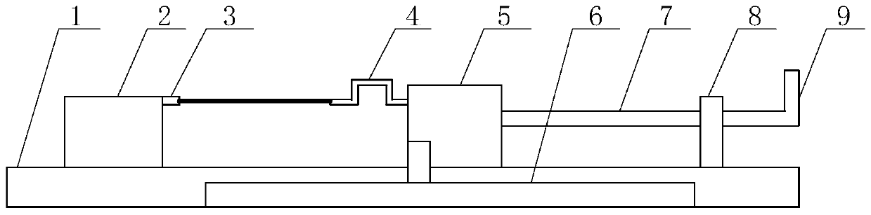
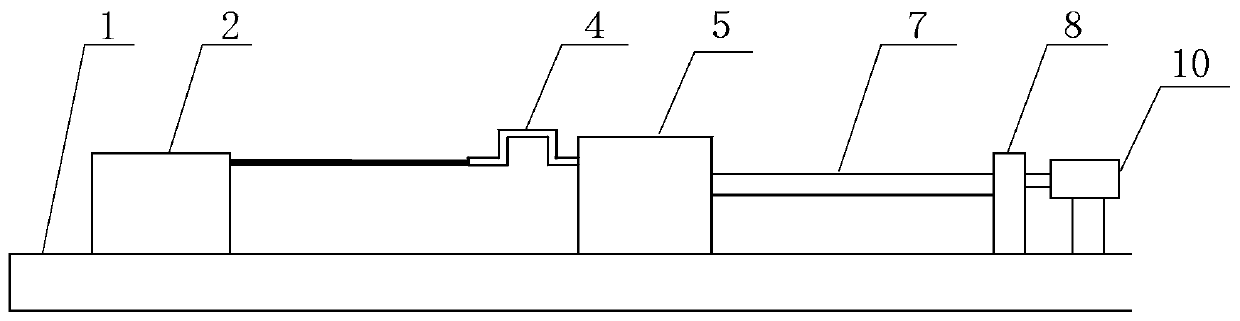
[0025] Step S11 sets up the force-deformation test platform of the stay rope, such as fi...


PUM


Abstract

The invention provides a dynamic measurement error compensation method based on a pull rope encoder measuring system. The method comprises the following steps that a relation database of pull rope deformation and stress is built; a relation database of pull rope acceleration speed and stress is built; the actual displacement of the tail end of the pull rope is obtained through calculation according to the relation database of the pull rope deformation and stress and the relation database of the pull rope acceleration speed and stress. According to the dynamic measurement error compensation method, a force measurement sensor does not need to be independently added in an original measuring system, the pull rope deformation caused by the acceleration speed of a measured object can be compensated in the dynamic measurement process, dynamic measurement precision is improved, the calculation process is simple, and implementation is easy.

Description

technical field [0001] The invention relates to the field of dynamic measurement, in particular to a dynamic measurement error compensation method based on a cable-drawing encoder measurement system. Background technique [0002] The three-coordinate measuring instrument is a common large-scale three-dimensional measurement system for space measurement, which can measure the surface characteristic parameters of the workpiece with high precision, but the disadvantages of this system are that it is too bulky, expensive, and inconvenient to move. The other is the commonly used laser tracker, which has high measurement accuracy and wide measurement range, but its dynamic measurement speed is limited and the price is too expensive. The dynamic measurement technology based on the high-precision rope encoder has been researched and applied. However, when measuring the three-dimensional coordinates of space, for the application occasions where the motion acceleration of the measured...

Claims


Application Information

Patent Timeline
Patent Type & Authority Patents(China)
IPC IPC(8): G01B21/00
CPCG01B21/00
Inventor 张得礼王珉陶克梅丁力平陈文亮王谢苗洪伟松潘国威周伟王夫康
Owner NANJING UNIV OF AERONAUTICS & ASTRONAUTICS
Why Eureka
Try Eureka