Optical coupling phenomenon demonstration instrument
A demonstration instrument and phenomenon technology, applied in the field of optical coupling phenomenon demonstration instrument, can solve the problems of no instrument, etc., and achieve the effect of intuitive image, convenient carrying, and intuitive demonstration
- Summary
- Abstract
- Description
- Claims
- Application Information
AI Technical Summary
Problems solved by technology
Method used
Image
Examples
Embodiment Construction
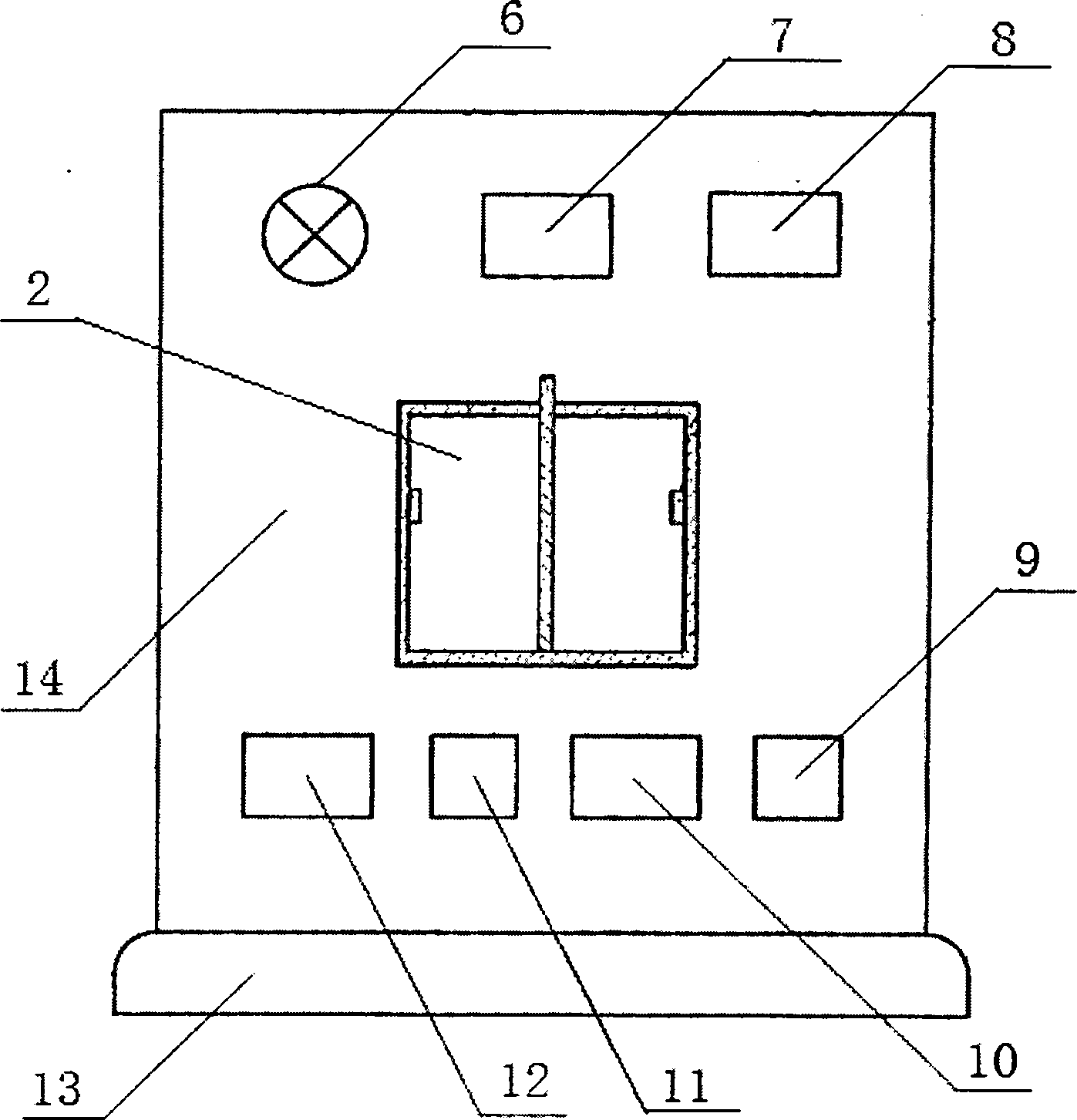
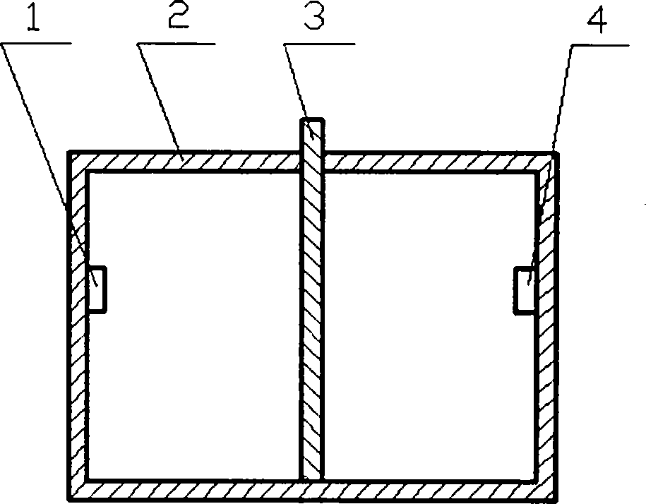
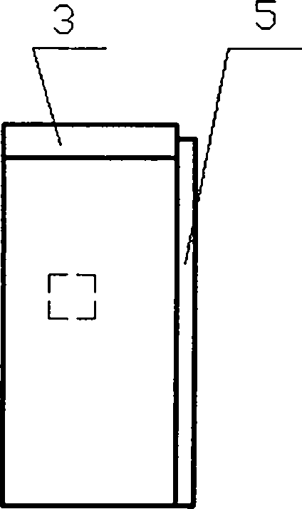
[0013] DC power supply (E 1 ) through the power switch (S 1 ), resistance (R 1 ) Apply the voltage between the anode and cathode of the light-emitting diode (VD), the DC power supply (E 2 ) through the power switch (S 2 ), resistance (R 2 ), resistance (R 3 ), resistance (R 4 ) to the phototransistor (VT 1 ), triode (VT 2 ) power supply, phototransistor (VT 1 ) emitter and transistor (VT 2 ) is connected to the base, and the ohmmeter (Ω) is connected to the cathode of the light-emitting diode (VD) and the phototransistor (VT 1 ) is used to demonstrate the isolation phenomenon between the emitters, and the bulb (H) is connected in series with the triode (VT 2 ) on the collector, the voltmeter (V) and the triode (VT 2 ) of the emitter resistance (R 4 ) in parallel, use a bulb (H) and a voltmeter (V) to demonstrate and measure the phototransistor (VT 1 ) status and data. Light-emitting diode (VD) and phototransistor (VT 1 ) is placed on the left and right sides in ...
PUM
 Abstract
Description
Claims
Application Information
 - R&D Engineer
- R&D Manager
- IP Professional
- Industry Leading Data Capabilities
- Powerful AI technology
- Patent DNA Extraction
Browse by: Latest US Patents, China's latest patents, Technical Efficacy Thesaurus, Application Domain, Technology Topic, Popular Technical Reports.
© 2024 PatSnap. All rights reserved.Legal|Privacy policy|Modern Slavery Act Transparency Statement|Sitemap|About US| Contact US: help@patsnap.com


