
Sparsity Adaptive Signal Reconstruction Method

An adaptive signal and sparsity technology, applied in electrical components, code conversion, etc., can solve the problems of reduced value, unknown signal sparsity, etc., and achieve the effect of accurate reconstruction

Active Publication Date: 2017-12-22
UNIV OF ELECTRONICS SCI & TECH OF CHINA
View PDF6 Cites 0 Cited by
  • Summary
  • Abstract
  • Description
  • Claims
  • Application Information

AI Technical Summary

Problems solved by technology

However, in practical problems, the sparsity of signals is often unknown, which greatly reduces the value of traditional greedy reconstruction methods in signal reconstruction applications.

Method used


Image

  • Sparsity Adaptive Signal Reconstruction Method

Examples


Embodiment Construction

[0021] The technical solution of the present invention will be described in detail below in conjunction with the accompanying drawings.

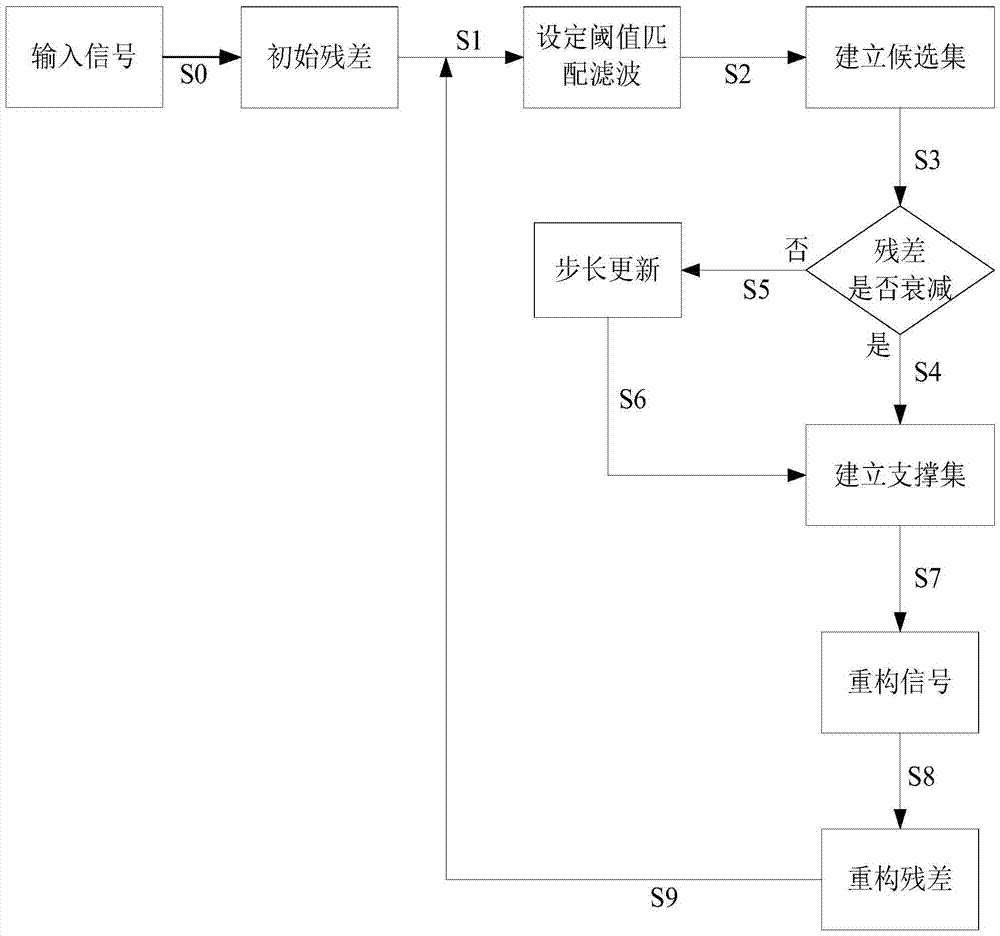
[0022] The invention adopts self-adaptive variable step length to estimate the sparsity degree of the signal. On this basis, the present invention first uses the input signal as the residual, and then performs matching filtering on the input signal according to the size of the set threshold, and then uses the obtained atoms to establish a candidate set, and then judges the pairing step according to the residual attenuation. The support set is obtained by updating for a long time, and finally the signal reconstruction is realized according to the new support set.

[0023] The sparsity adaptive signal reconstruction method of the present invention is a cyclic and iterative process, where k represents the kth iteration, k=1, 2...N, and its flow is as follows figure 1 shown, including the following steps:

[0024] Step S0, taking the input sig...


PUM


Abstract

The present invention relates to signal processing techniques. The invention discloses a sparsity self-adaptive signal reconstruction method, comprising steps: S0, taking the input signal as a residual; S1, setting a threshold according to the residual, and performing matching filtering to obtain an atom Jk related to the signal; S2, using The atoms obtained in the step S1 establish a candidate set; S3, determine whether the residual is attenuated; S4, if the determination in the step S3 is yes, then use the candidate set obtained in the step S2 to establish a support set, and go to step S7; S5 , if the step S3 judges as no, then update the step size; S6, use the step size obtained in the step S5 to establish a support set, and enter step S7; S7, approximate the signal according to the support set, and obtain the reconstructed signal ; S8, using the reconstruction signal obtained in step S7 to calculate the reconstruction residual; S9, return to step S1, and use the reconstruction residual obtained in step S8 as the residual to perform loop iterations until two consecutive reconstruction residuals If it is less than a given value, the best reconstructed signal is obtained. The invention can carry out accurate reconstruction under the condition of unknown signal sparsity.

Description

technical field [0001] The invention relates to the technical fields of compressed sensing and signal processing, in particular to a sparsity adaptive signal reconstruction method based on segmented orthogonal matching tracking. Background technique [0002] In signal processing technology, the traditional greedy reconstruction method has matching pursuit (Matching Pursuit, abbreviated as MP. See MALLAT S, ZHANG Z.Matching Pursuit with time-frequency dictionaries[J].IEEE Trans.Sig.Proc.,1993, 41(12):3397-3415.), Orthogonal Matching Pursuit (Orthogonal Matching Pursuit, abbreviated as OMP. See TROPP J, GILBERT A. Signal recovery from random measurements via orthogonal matching pursuit [J]. IEEE Transactions on Information Theory, 2007, 53 (12): 4655-4666.), Compressive Sampling MP (CompressiveSampling MP, abbreviated as CoSaMP see NEEDELL D, TROPP J A. CoSaMP: Iterative signal recovery from incomplete and inaccurate samples [J]. Applied and Computational Harmonic Analysis, 20...

Claims


Application Information

Patent Timeline
Patent Type & Authority Patents(China)
IPC IPC(8): H03M7/30
Inventor 陈勇冷佳旭张立波
Owner UNIV OF ELECTRONICS SCI & TECH OF CHINA
Learn More