A method for visually controlling video equipment applied to switches

A technology of video equipment and switches, which is applied in the field of communication networks, can solve the problems that do not involve video surveillance equipment storage equipment, etc., and achieve the effect of convenient management, convenient use, and good visualization

Active Publication Date: 2017-07-28
深圳市磊科实业有限公司
View PDF6 Cites 0 Cited by
  • Summary
  • Abstract
  • Description
  • Claims
  • Application Information

AI Technical Summary

Problems solved by technology

In order to effectively manage video surveillance equipment and storage equipment in real time, how to identify the status, port location, and relationship between video surveillance equipment and storage equipment through switches or even across switches is a key problem that needs to be solved. The invention has not yet involved the identification of video surveillance equipment and storage equipment

Method used


Image

  • A method for visually controlling video equipment applied to switches
  • A method for visually controlling video equipment applied to switches
  • A method for visually controlling video equipment applied to switches

Examples


Embodiment

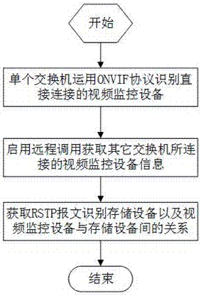
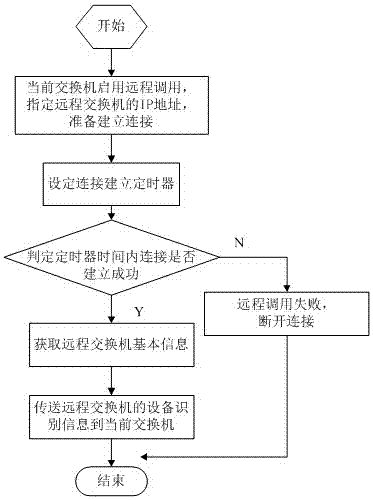
[0052] Such as Figure 1 to Figure 6As shown, the method for visually controlling video equipment is mainly applied to the gateway equipment of the scalable open intelligent gateway platform, such as a switch, and a certain network includes 3 switch switches, 8 video monitoring equipment ipc and 2 storage devices Take nvr as an example, where SwitchX represents the number of the switch, ipcX represents the number of the monitoring device, nvrX represents the number of the storage device, and the number X represents the switch port. It is assumed that the video surveillance devices managed by the storage device nvr1 are ipc1, ipc2, ipc3, ipc4, and ipc5, and the video surveillance devices managed by the storage device nvr2 are ipc6, ipc7, and ipc8. It should be noted that the cascading port of the switch does not process packets (for example, ports 5 and 6 of Switch A; port 1 of Switch B; port 1 of Switch C is the cascading port). The present invention specifically comprises th...


PUM


Abstract

The invention discloses a method for visually controlling video equipment applied to a switch, including (S10) a single switch using the ONVIF protocol to identify the video monitoring equipment directly connected to it; (S20) enabling remote calls to obtain other switches connected Video monitoring device information; (S30) Obtaining rtsp messages to identify the storage device and the relationship between the video monitoring device and the storage device; (S40) The switch visually displays the identified result. The present invention is ingeniously conceived, effectively utilizes the ONVIF and rtsp protocols to identify the video monitoring equipment and storage equipment connected to the switch, and can obtain the state of the corresponding equipment, the port position and the relationship between the equipment in real time, and the present invention is convenient Management can maintain a many-to-many relationship, which helps network managers to quickly configure the network and locate network faults. It has high practical value and promotion value.

Description

technical field [0001] The invention belongs to the technical field of communication networks, and in particular relates to a method for visually identifying video surveillance equipment and its storage equipment applied to switches. Background technique [0002] Video surveillance is an important part of the security system. Video surveillance is widely used in many occasions because of its intuition, accuracy, timeliness and rich information content. In recent years, with the rapid improvement of network bandwidth, computer processing power and storage capacity, and the emergence of various video information processing technologies, the advantages of the whole digital and networked video surveillance system have become increasingly prominent. Its high degree of openness, integration and Flexibility creates the necessary conditions for the overall performance improvement of video surveillance equipment. At this time, signal transmission mainly uses network signal transmissi...

Claims


Application Information

Patent Timeline
Patent Type & Authority Patents(China)
IPC IPC(8): H04L12/26H04L12/24
Inventor 王涛李可
Owner 深圳市磊科实业有限公司
Why Eureka
Try Eureka