Water return mechanism of steam cleaner and steam cleaner
A technology of cleaning machine and steam, applied in the field of steam cleaning machine
- Summary
- Abstract
- Description
- Claims
- Application Information
AI Technical Summary
Problems solved by technology
Method used
Image

Examples
Embodiment 1
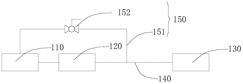
[0030] The pipeline diagram of the water return mechanism of the steam cleaner of an embodiment is as follows: figure 1 As shown, the steam cleaner includes a water storage tank 110 , a water pump 120 communicated with the water tank 110 , and a boiler 130 communicated with the water pump 120 . The pipeline connecting the water pump 120 and the boiler 130 is a water inlet pipeline 140 , and a water return mechanism 150 is arranged between the water storage tank 110 and the water inlet pipeline 140 . The water return mechanism 150 includes a water return pipeline 151 and a valve 152 arranged on the water return pipeline 151 for controlling the switch of the water return pipeline 151 .
[0031] When the steam cleaner starts to work, the water in the water storage tank 110 enters the boiler 130 from the water inlet pipe 140 via the water pump 120 , and then forms steam in the boiler 130 to be ejected to achieve the purpose of use. At this time, the valve 152 on the return water ...
Embodiment 2
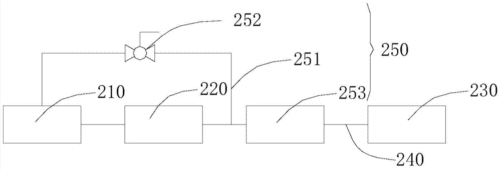
[0034] The pipeline diagram of the water return mechanism of the steam cleaner of an embodiment is as follows: figure 2 As shown, the steam cleaner includes a water storage tank 210 , a water pump 220 and a boiler 230 communicating with the water storage tank 210 . The pipeline between the water pump 220 and the boiler 230 is the main water inlet pipeline 240 , and a water return mechanism 250 is set between the water storage tank 210 and the main water inlet pipeline 240 . The water return mechanism 250 includes a return water pipeline 251 and a valve 252 arranged on the water return pipeline 251 to control the switch of the water return pipeline 251 . In addition, a buffer chamber 253 is provided between the water return pipeline 251 and the boiler 230 . The buffer cavity 253 can be a pipe with a smooth inner wall, and the diameter of the pipe is larger than that of the main water inlet pipeline and the return water pipeline. The above-mentioned buffer chamber 253 is used ...
Embodiment 3
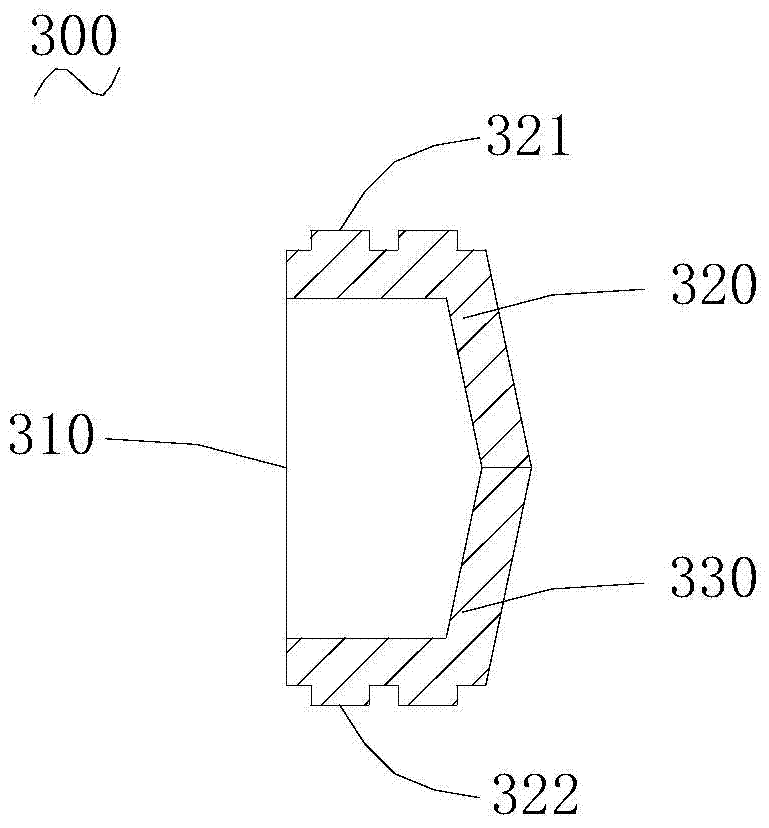
[0042] The steam cleaner in one embodiment includes a water pump 320 , a boiler 330 and a water return mechanism 350 disposed between the water pump 320 and the boiler 330 . The water return mechanism 350 includes a return water line 351 , a valve 352 arranged on the return water line 351 to control the switch of the return water line 351 , and a buffer chamber 353 arranged between the return water line and the boiler. The pipeline through which the water pump 320 feeds water into the boiler 330 is the main water inlet pipeline 340 . The buffer cavity can be a pipe with a smooth inner wall, and the diameter of the pipe is larger than that of the main water inlet pipeline and the return water pipeline. The above-mentioned buffer cavity is used to accommodate reversely released water and steam.
[0043] In this embodiment, the piston 500 disposed in the buffer cavity 353 is a closed type, that is, the piston 500 cannot allow water and steam to pass through. At this time, it is...
PUM
 Abstract
Description
Claims
Application Information
 - R&D
- Intellectual Property
- Life Sciences
- Materials
- Tech Scout
- Unparalleled Data Quality
- Higher Quality Content
- 60% Fewer Hallucinations
Browse by: Latest US Patents, China's latest patents, Technical Efficacy Thesaurus, Application Domain, Technology Topic, Popular Technical Reports.
© 2025 PatSnap. All rights reserved.Legal|Privacy policy|Modern Slavery Act Transparency Statement|Sitemap|About US| Contact US: help@patsnap.com