Ventilation navigation body self-rotation device used in water tunnel experiment

A flying body and experimental technology, applied to measuring devices, transportation and packaging, fluid dynamics tests, etc., can solve the problems of large power supply power devices, unsatisfactory experimental results, and inability to install cables, etc., achieving low manufacturing costs and applicable Wide-ranging, manufacturing-cost-saving effects

Inactive Publication Date: 2015-02-04
HARBIN INST OF TECH
View PDF7 Cites 4 Cited by
  • Summary
  • Abstract
  • Description
  • Claims
  • Application Information

AI Technical Summary

Problems solved by technology

[0004] The present invention provides a kind of spin device of ventilated sailing body in water tunnel experiment, in order to solve the poor flexibility of the existing ventilated sailing body model in the water tunnel experiment, the experimental effect is not ideal and the power supply power device required for spinning is large in size and fixed. An issue where the vent lines and cables could not be placed inside the ventilated vehicle model for spinning

Method used


Image

  • Ventilation navigation body self-rotation device used in water tunnel experiment
  • Ventilation navigation body self-rotation device used in water tunnel experiment
  • Ventilation navigation body self-rotation device used in water tunnel experiment

Examples


specific Embodiment approach 1

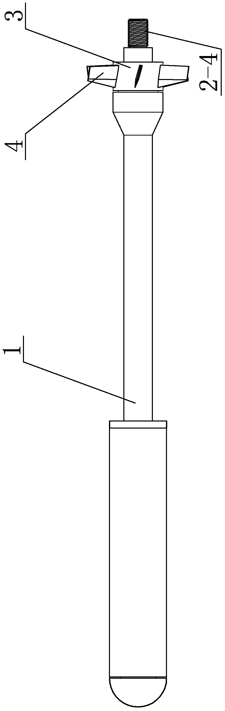
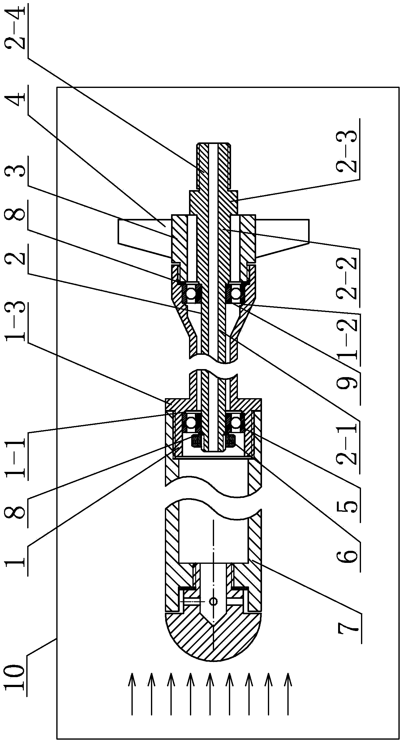
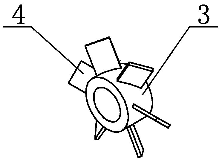
[0013] Specific implementation mode one: combine figure 1 , figure 2 , image 3 , Figure 4 , Figure 5 , Image 6 , Figure 7 and Figure 8 To illustrate this embodiment, a water tunnel experiment ventilating flying body spin device described in this embodiment includes an outer support tube 1, an inner support tube 2, a propeller casing 3, a first waterproof bearing 5, a second waterproof bearing 9 and A plurality of propeller blades 4, the front end of the outer support tube 1 is detachably connected to the ventilating vehicle model 7, the rear end of the outer support tube 1 is detachably connected to the propeller casing 3, and the outer wall of the propeller casing 3 A plurality of propeller blades 4 are fixedly connected to the top, and one end of the inner support pipe 2 is arranged inside the outer support pipe 1 through the propeller casing 3, the inner support pipe 2 and the propeller casing 3 are arranged in a gap, and the inner support The tube 2 is fitted...

specific Embodiment approach 2

[0016] Specific implementation mode two: combination figure 2 Describe this embodiment, the inner support pipe 2 in this embodiment is composed of the first section of pipe body 2-1, the second section of pipe body 2-2, the third section of pipe body 2-3 and the fourth section of pipe body 2- 4. The head and tail are fixedly connected in sequence, and the outer diameters of the first section of pipe body 2-1, the second section of pipe body 2-2 and the third section of pipe body 2-3 increase sequentially, and the first waterproof The bearing 5 is set on the first section of the tube body 2-1, the outer end surface of the first waterproof bearing 5 is fixedly connected with the inner wall of the outer support tube 1, and the inner end surface of the first waterproof bearing 5 is connected with the inner wall of the inner support tube 1. The outer wall gap is set; the rear end surface of the second waterproof bearing 9 is closely attached to the second section of the pipe body ...

specific Embodiment approach 3

[0020] Specific implementation mode three: combination figure 1 and figure 2 Describe this embodiment, in this embodiment, the tube outer diameter of one end of the outer support tube 1 is 32-36 mm and the outer diameter of the tube is processed with external thread, and the tube inner diameter of the other end of the outer support tube 1 is 28-36 mm. 32mm and internal threads are processed on the inner diameter of the tube.

[0021]In this embodiment, the size setting of the tube outer diameter at one end of the outer support tube 1 is specifically set in order to match the tail end inner diameter of the existing ventilating vehicle model 7, and at the same time, the tube outer diameter at one end of the outer support tube 1 is processed. The external thread is for realizing the threaded connection between the external support pipe 1 and the ventilating vehicle model 7 . In the same way, the size setting of the tube inner diameter at the other end of the outer support tube...


PUM


Abstract

The invention discloses a ventilation navigation body self-rotation device used in water tunnel experiment, and relates to a self-rotation device, aiming at solving the problems that a conventional ventilation navigation body model used in water tunnel experiment is poor in flexibility, the experiment effect is not ideal, the size of a power supply device needed for self-rotation is large, and a fixed ventilation pipeline and a cable cannot be arranged inside the ventilation navigation body model for self-rotation. The front end of an external support tube is detachably connected with the ventilation navigation body model; the rear end of the external support tube is detachably connected with a propeller sleeve body; a plurality of propeller blades are arranged on the outer wall of the propeller sleeve body; one end of an internal support tube penetrates through the propeller sleeve body and is arranged inside the external support tube; a first waterproof bearing and a second waterproof bearing sleeve the internal support tube; a first baffle edge and a second baffle edge are respectively arranged on the inner wall of the front end and the inner wall of the rear end of the external support tube; the rear end surface of the first waterproof bearing is tightly adhered to the first baffle edge; the front end surface of the second waterproof bearing is tightly adhered to the second baffle edge. The ventilation navigation body self-rotation device is used for assisting a ventilation navigation body to rotate by self.

Description

technical field [0001] The invention specifically relates to a spinning device for a ventilated sailing body in a water tunnel experiment. Background technique [0002] Carrying out model scaling experiments is an important method to study the hydrodynamic characteristics of underwater vehicles. In order to improve the hydrodynamic environment of underwater vehicles, ventilation slots are often designed on the head of the vehicle, relying on the gas released from the ventilation slots. Form air bubbles wrapping the vehicle, or design and use a circle of small air holes on the head of the vehicle to form an air curtain that wraps the vehicle. In order to check the shape of the cavitation or air curtain formed by the ventilation when the vehicle is spinning, it is necessary for the support rod of the ventilation vehicle model to drive the vehicle to achieve the rotation effect, and to meet the function of introducing gas into the interior of the vehicle. . [0003] The water...

Claims


Application Information

Patent Timeline
Patent Type & Authority Applications(China)
IPC IPC(8): B63B9/00G01M10/00
Inventor 王聪王威曹伟张孝石
Owner HARBIN INST OF TECH
Why Eureka
Try Eureka