Pushing and setting device

一种推靠臂、密封堵的技术,应用在井眼/井部件、土方钻采等方向,能够解决探头与地层接触面积小、不能直接提拉仪器、探头不能实现均匀接触井壁等问题

Active Publication Date: 2015-02-04
XIAN ZHENYU ELECTRON ENG CO LTD
View PDF5 Cites 11 Cited by
  • Summary
  • Abstract
  • Description
  • Claims
  • Application Information

AI Technical Summary

Problems solved by technology

[0003] At present, the formation pressure measurement and fluid sampling tools that appear on the market use piston-cylinder probes. The biggest disadvantage of this structure is that the contact area between the probe and the formation is too small, and the instrument cannot be pulled directly, and it is easy to get stuck in the oil well. At the same time, the probe with this structure cannot achieve uniform contact with the well wall along the radial direction, nor can it control the force of pushing against the well wall

Method used


Image

  • Pushing and setting device
  • Pushing and setting device
  • Pushing and setting device

Examples


Embodiment Construction

[0026] In order to better understand the purpose and function of the present invention, the structure and working process of a specific embodiment of the present invention will be described in detail below in conjunction with the accompanying drawings.

[0027] In order to overcome the shortcomings in the prior art, the three-arm seat seal pusher for oil exploration described in this embodiment includes three push-back pistons and fluid passages on the left part, three six-rod structures in the middle and other The inner fluid channel, the three push pistons and the fluid channel on the right part, also includes the upper and lower electrical connection multi-core guide joints.

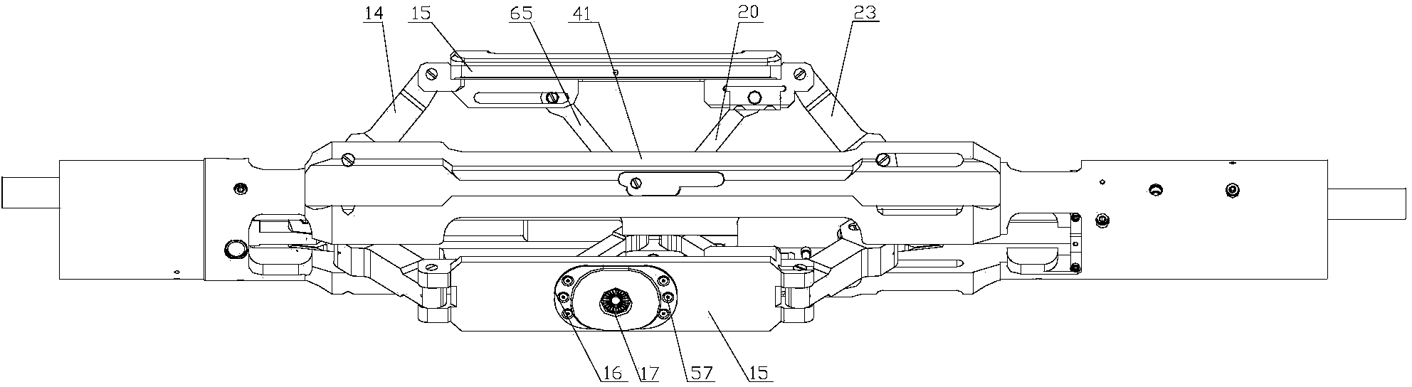
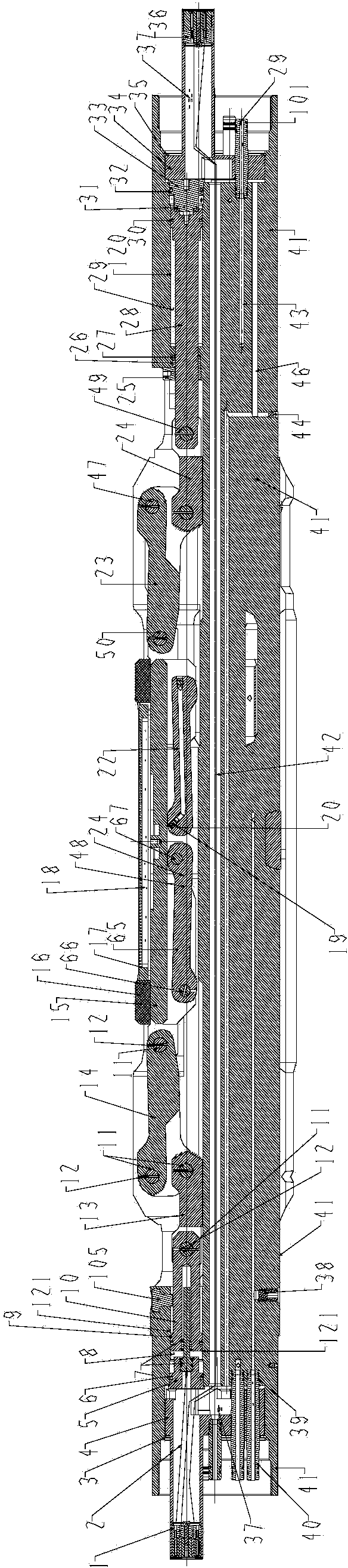
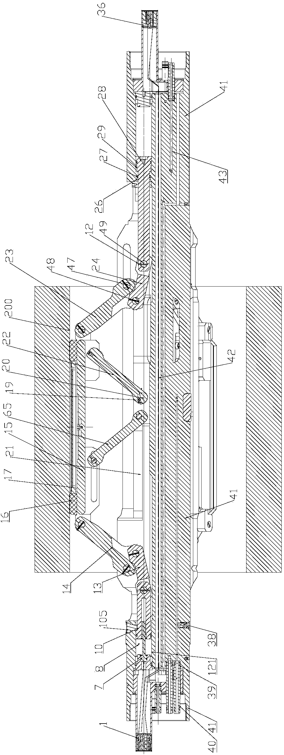
[0028] Such as figure 1 As shown, the pushing and setting device in this embodiment includes three sets of pushing arms uniformly and radially arranged on the main base 41, and the three pushing pistons driven by the hydraulic cylinder respectively move, and the three pushing pistons The three pushin...


PUM


Abstract

The invention provides a pushing and setting device for oil exploitation. The pushing and setting device comprises a main substrate (41); one or more than one group of pushing arms are arranged at the periphery of the main substrate; each group of pushing arms are of a double parallelogram structure; a front pushing arm (14), a sealing probe body (15), an auxiliary pushing arm (20) and the main substrate form a first parallelogram structure; the front pushing arm (14) is respectively connected with the sealing probe body (15) and the main substrate through connecting shafts (11); two ends of the auxiliary pushing arm (20) are respectively connected with the sealing probe body (15) and the main substrate through rotating shafts; a back pushing arm (23), the sealing probe body (15), a holeless auxiliary arm (65) and the main substrate form a second parallelogram structure through connecting shafts. The pushing and setting device with the structure can be in contact with the wall of a well uniformly and can also control the force for pushing the wall of the well.

Description

technical field [0001] The invention relates to a petroleum exploration tool, in particular to a pushing and setting device for exploring the internal fluid pressure of formations and obtaining formation fluid samples. Background technique [0002] In the process of oil development, it is necessary to measure the fluid pressure inside the formation and take samples of the formation fluid to accurately determine the position of the oil layer and facilitate oil extraction. [0003] At present, the formation pressure measurement and fluid sampling tools that appear on the market use piston-cylinder probes. The biggest disadvantage of this structure is that the contact area between the probe and the formation is too small, and the instrument cannot be pulled directly, and it is easy to get stuck in the oil well. At the same time, the probe with this structure cannot achieve uniform contact with the well wall along the radial direction, nor can it control the force of pushing aga...

Claims


Application Information

Patent Timeline
Patent Type & Authority Applications(China)
IPC IPC(8): E21B49/00E21B49/08
CPCE21B49/10E21B49/00E21B49/087
Inventor 王少斌
Owner XIAN ZHENYU ELECTRON ENG CO LTD
Why Eureka
Try Eureka