Adhesive-treated electrode separator and method of adhering an electrode thereto

a separator and adhesive technology, applied in the direction of cell components, electrochemical generators, cell component details, etc., can solve the problem of tacky polymer components, achieve the effect of maximizing electrode efficiency, reducing the amount of adhesive required, and maximizing surface area

Inactive Publication Date: 2005-11-24
ELDOR CORP SPA
View PDF1 Cites 22 Cited by
  • Summary
  • Abstract
  • Description
  • Claims
  • Application Information

AI Technical Summary

Benefits of technology

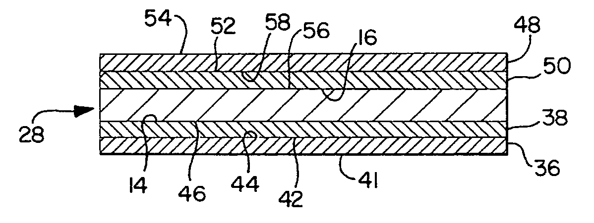
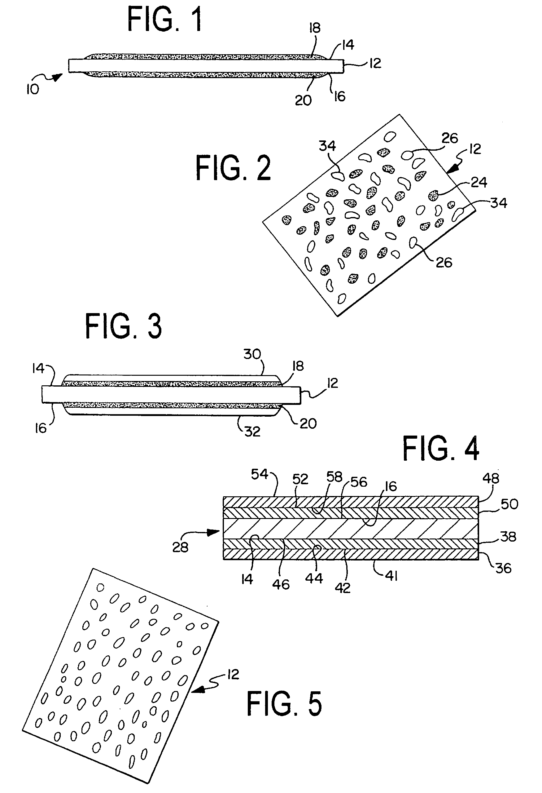
[0025] In the above method, the first and second adhesive formulations are coated on the separator by spraying, a micro-gravure process, dip coating, or any other suitable means. During the coating step, the occlusion prevention component of each adhesive formulation substantially plugs the pores of the separator and substantially prevents the adhesive component from filling the same pores. Because the pores of the separator are substantially blocked by the occlusion prevention component, the insoluble adhesive is maintained on the surface of the separator where it can most efficiently come into contact with the electrodes to be adhered. When the occlusion prevention component is removed via melting or evaporating, preferably during the lamination step, the pores become substantially free of occlusions. Thus, in a closed electrochemical cell, ions may efficiently pass through the separator pores while the bulk of the adhesive is maintained outside the pores. Thus, the adhesive-treated separator membrane and method for adhering an electrode to the separator reduce the amount of adhesive required, maximize electrode efficiency, and enable the production of free form batteries which maximize surface area.

Problems solved by technology

This second component promotes adhesion since it will melt during the heat lamination step thus making the polymer component tacky.

Method used


Image

  • Adhesive-treated electrode separator and method of adhering an electrode thereto
  • Adhesive-treated electrode separator and method of adhering an electrode thereto
  • Adhesive-treated electrode separator and method of adhering an electrode thereto

Examples


example 1

[0064] Different concentration of PEO (polyethylene oxide) and PVdF (polyvinylidene fluoride) solutions were prepared as given in Table 1. As seen in Table 1, PEO and PVdF concentrations investigated in this work are in range from 1-3 wt %. Solutions that were opaque were stirred on hot plate until turn clear.

TABLE 1PEO (polyethylene oxide) and PVdF(polyvinylidene fluoride) SolutionsPolymer SolutionOpacity1% w / w PEO in γBLClear2% w / w PEO in γBLClear3% w / w PEO in γBLOpaque1% w / w PEO in EC:DMC = 3:7 w / wClear2% w / w PEO in EC:DMC = 3:7 w / wOpaque3% w / w PEO in EC:DMC = 3:7 w / wOpaque1% w / w Kynar 2801 in γBLClear2% w / w Kynar 2801 in γBLClear3% w / w Kynar 2801 in γBLClear1% w / w Kynar 2801 in EC:DMC = 3:7 w / wClear2% w / w Kynar 2801 in EC:DMC = 3:7 w / wClear3% w / w Kynar 2801 in EC:DMC = 3:7 w / wClear

[0065] Polymer solutions were sprayed on electrodes of area 41.76 cm2 by using an airbrush. A strip of Celgard 2500 as a separator was placed in between two electrodes. Lamination was achieved by pas...

example 2

[0074] Instead of coating an adhesive on the electrodes, a solvent is coated on the electrode in order to soften the polymer binder in the electrode and to make it adhesive.

[0075] Electrodes used in the experiments were cathode: PL50(761A), 88-6-6 and anode: QC4100 (Kynar 761A), 91-3-6. The electrodes active area was 41.76 cm2 (‘3 strips’).

[0076] Different amounts of γBL were sprayed on the electrodes using an air-brush. Special attention was given to the uniformity of spraying, which covered the electrode as well as would be achieved by hand air-brushing. Each electrode was weighted before and immediately after applying the solvent. Table 2 gives the amounts of the solvent applied. A strip of Celgard 2500 as a separator was placed in between two electrodes, and lamination was achieved by passing the assembled stack through a laminator at ˜110 C.

[0077] After overnight vacuum drying, the activation of the cells was done in a glove box by soaking the cells in an excess of electroly...

example 3

A battery was formed using the following procedure:

[0083] 1) Prepare a PEMA polymer blend in THF solvent mixture under heating and stirring. [0084] 2) Coat Celgard 2500 in PEMA blend solution for 1˜3 minutes and then dry in air. [0085] 3) Laminate cathode, coated separator, and anode under lower power setting. [0086] 4) Dry in 60° C. oven under vacuum for overnight or more to completely remove THF. [0087] 5) Soak lamination stack in electrolyte SR40 for at least 1 hrs. [0088] 6) Vacuum sealing into prismatic cells.

[0089] It was found:

[0090] (a) PEMA dissolves in hot THF, not in NMP, acetone and carbonate solvent such as EC, DEC and DMC;

[0091] (b) having high boiling points, γBL, EC and PC were used in solvent mixtures in order to leave pores open in coated separator;

[0092] (c) PEMA showed good adhesion between electrodes and separators. No delamination was observed in the cells with PEMA / PEO, PEMA / PMMA blend coated separator after soaking in electrolyte for 2 hrs;

[0093] (d) G...


PUM

PropertyMeasurementUnit
melting pointaaaaaaaaaa
areaaaaaaaaaaa

Abstract

An adhesive-treated porous separator and a method of adhering an electrode to the adhesive-treated separator without substantially occluding the pores of the separator. The adhesive-treated separator membrane comprises a porous separator having an anode side and a cathode side, a first adhesive formulation coated on the anode side, and a second adhesive formulation coated on the cathode side. The first and second adhesive formulations each include an adhesive component, a solvent, and an occlusion prevention component. The method of adhering the electrode to the adhesive-treated separator includes the steps of providing the first adhesive formulation and the second adhesive formulation, providing a porous separator having an anode side and a cathode side; coating the anode side of the separator with the first adhesive formulation and coating the cathode side of the separator with the second adhesive formulation such that the occlusion prevention component substantially fills the pores of the separator; precluding occlusions in the pores of the separator so as to substantially free the pores of occlusions; and laminating an anode to the anode side and a cathode to the cathode side of the separator.

Description

TECHNICAL FIELD [0001] The present invention relates generally to an adhesive-treated separator and a method for adhering an electrode to the adhesive-treated separator in a lithium ion electrochemical cell without substantially occluding the pores of the separator. BACKGROUND OF THE INVENTION [0002] Lithium ion electrochemical cells are known in the art. Such cells or batteries generally include an electrolyte, an anode, and a cathode. During fabrication of the cell, the anode and cathode are adhered to or are otherwise brought into contact with a separator. The quality of the electrodes' adhesion or contact with the separator has a significant impact on battery performance. For example, poor adhesion or contact of the electrodes to the separator may negatively affect the electrical continuity of the cell, increase resistance within the cell, or may reduce the number of possible geometries the cell can be formed into. There are a number of known methods for adhering or adjoining el...

Claims


Application Information

Patent Timeline
Patent Type & Authority Applications(United States)
IPC IPC(8): H01M10/0525H01M50/403H01M50/443H01M50/463H01M50/466
CPCH01M2/145H01M2/16Y10T29/49114H01M2/18H01M10/0525H01M2/168Y02E60/10H01M50/461H01M50/403H01M50/463H01M50/466H01M50/443
Inventor PERSI, LUIGIVANBUREN, MARTINFAUTEUX, DENIS G.
Owner ELDOR CORP SPA
Why Eureka
Try Eureka