Method for reducing three-coordinate measuring compensating error of blade surface

A three-coordinate measurement and error compensation technology, applied in the field of measurement, can solve the problems of large cosine error and affect the accuracy of measurement evaluation, etc., and achieve the effect of solving the problem of cosine error

Inactive Publication Date: 2015-02-04
SHENYANG LIMING AERO-ENGINE GROUP CORPORATION
View PDF6 Cites 10 Cited by
  • Summary
  • Abstract
  • Description
  • Claims
  • Application Information

AI Technical Summary

Problems solved by technology

[0003] In the three-coordinate measurement of the profile of the end-curved blade, since the contact point between the actual probe and the blade is not completely consistent with the contact point calculated by the software, the resulting error value i

Method used


Image

  • Method for reducing three-coordinate measuring compensating error of blade surface
  • Method for reducing three-coordinate measuring compensating error of blade surface
  • Method for reducing three-coordinate measuring compensating error of blade surface

Examples


Embodiment Construction

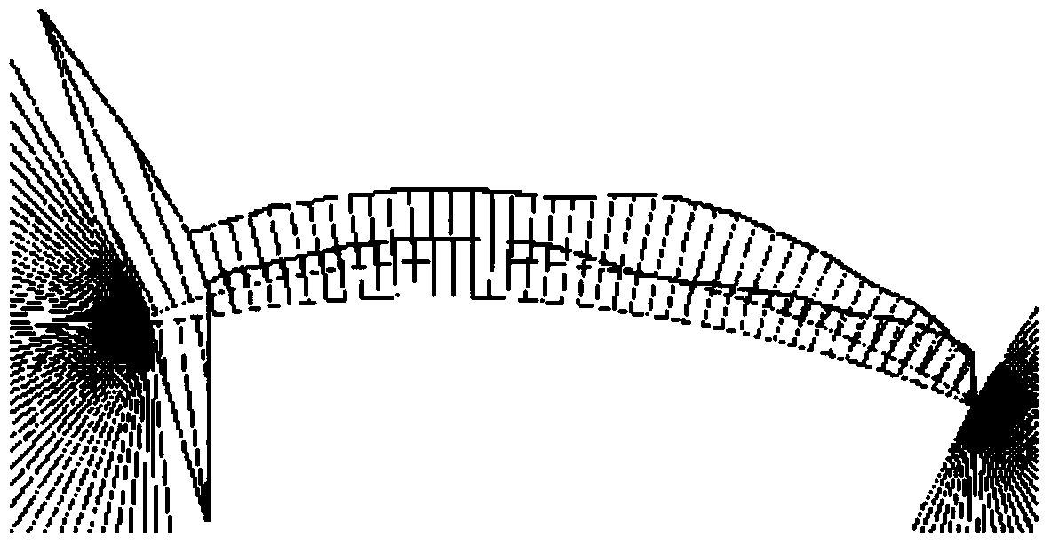
[0025] The present invention is specifically described below in conjunction with accompanying drawing, as Figure 1-Figure 5 As shown, according to the problem of cosine error in the two-dimensional cross-sectional scanning of a certain end-curved blade using a three-dimensional coordinate measuring machine, resulting in a large deviation of the measured data, the method of the present invention is used to measure the end-curved position. to reduce measurement errors.

[0026] The specific implementation method is:

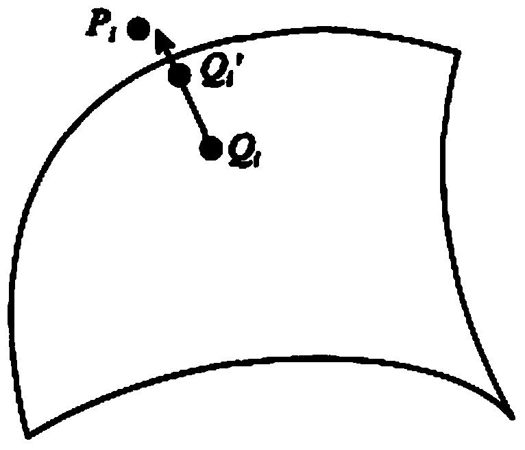
[0027] Make a new measurement surface

[0028] The vectors of each point of the blade body section are as follows: figure 1 As shown, the coordinates are shown in Table 1;

[0029] Table 1

[0030]

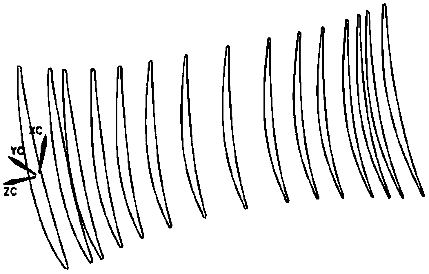
[0031] (1) According to the X, Y, Z coordinates of the design drawing, make a section curve forming multiple sections;

[0032] #Z,-124.5

[0033] P1, X-46.4982, Y-6.9525

[0034] P2, X-43.9148, Y-6.6336

[0035] P3, X-41.4438, Y-6.1816

[0036] P4, X-39....


PUM


Abstract

The invention discloses a method for reducing three-coordinate measuring compensating error of a blade surface. The method is characterized by comprising the steps of manufacturing a new measuring curve and the comparing and analyzing the measuring deviation; the new measuring curve is specifically manufactured by the following steps: 1, manufacturing the two-dimensional graph of each section according to the theoretical point proposed by the design drawing; 2, generating a three-dimensional body surface through the plurality of two-dimensional graphics of the sections; 3, obtaining the closed measuring point of each section; 4, deviating the measuring point of each section by a probe radius along the normal direction to obtain the coordinate of a new measuring point; 5, generating a new section curve through the new measuring point; 6, connecting all sections produced according to the new measuring point, so as to obtain a new measuring curve. The method has the beneficial effects that the cosine measuring error of the body surface is controlled to be within 0.005, thus the problem of cosine error caused by the current two-dimensional surface measuring can be effectively solved, and the true deviation value of the surface of the end bending part is obtained.

Description

technical field [0001] The invention relates to a measurement technology, in particular to a three-coordinate measurement technology of an aeroengine blade profile. Background technique [0002] The blade profile measurement is generally evaluated by the profile deviation and position deviation of the characteristic section (design given section). These characteristic sections are based on a certain plane and have a specific section height. The intersection line of the section and the airfoil profile forms a set of closed plane two-dimensional curves, and this set of closed curves is the airfoil section line, which is the object of blade profile measurement. Although each section line is in the plane, since the normal direction of each measurement point on the section line is changing three-dimensionally, they cannot be treated as two-dimensional curves. It is for this reason that a difficult point in the measurement of the blade profile is caused, that is, the introduction...

Claims


Application Information

Patent Timeline
IPC IPC(8): G01B21/00G01B21/20
CPCG01B21/20
Inventor 宋成姜绍西李美荣陈亚莉段晓玲
Owner SHENYANG LIMING AERO-ENGINE GROUP CORPORATION
Why Eureka
Try Eureka