A liquid chromatograph

A liquid chromatograph and chromatographic column technology, which is applied in the field of liquid chromatographs with on-line cleaning function, can solve the problems of taking a long time and being unable to realize highly automated operation of the chromatograph.

Active Publication Date: 2015-12-02
HUNAN DEMETER INSTR CO LTD
View PDF5 Cites 2 Cited by
  • Summary
  • Abstract
  • Description
  • Claims
  • Application Information

AI Technical Summary

Problems solved by technology

However, this method has no effect on retaining strong impurities and tiny particles that cause chromatographic column failure; in addition, it takes a long time; and it cannot be carried out while analyzing samples, and it is also impossible to achieve highly automated operation of the chromatograph

Method used


Image

  • A liquid chromatograph
  • A liquid chromatograph
  • A liquid chromatograph

Examples


Embodiment 1

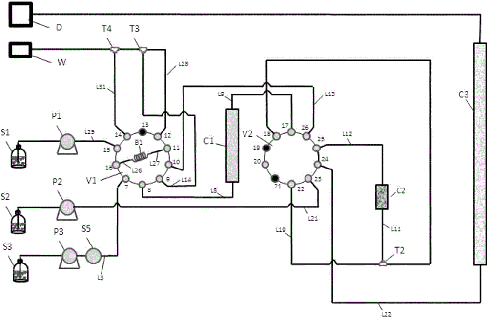
[0063] like figure 1 Shown, a kind of liquid chromatograph comprises:

[0064] The first flow channel L3 connected with the injector S5 is used to deliver the first mobile phase S3;

[0065] The second channel L21 is used to transport the second mobile phase S2;

[0066] The first chromatographic column C1 is used for primary separation of the sample;

[0067] The middle chromatographic column C2 is used to capture the substances separated by the first chromatographic column C1;

[0068] Analytical flow path L22, which includes a second chromatographic column C3 and a detector D connected in sequence, for further separation and detection of substances captured in the intermediate chromatographic column C2;

[0069] Waste liquid flow channels L28, L31, L14 are used to discharge waste liquid;

[0070] The cleaning channel L25, the directional switching valve V1 and the multi-channel switching valve V2 used to transport the cleaning solution S1; the first chromatographic colu...

Embodiment 2

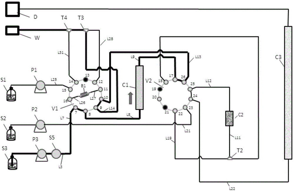
[0082] like Figure 8 Shown, a kind of liquid chromatograph, on the basis of the liquid chromatograph described in embodiment 1, also includes:

[0083] The modulating channel IL17 is used to deliver the modulating solution S4; and the modulating channel IL17 is connected to the port e21 of the multi-channel switching valve V2;

[0084] Modulation flow channel IIL18, one end of the modulation flow channel IIL18 is connected to the port d20 of the multi-channel switching valve V2, the other end of the modulation flow channel IIL18 is connected to the first flow channel L3, and connected to the flow channel after the injector S5 .

[0085] Function description: The liquid chromatograph described in embodiment 2, except having all functions of embodiment 1, also has the following special functions:

[0086] 1. The function of cleaning the first chromatographic column with the prepared solution:

[0087] like Figure 9 As shown, turn on the delivery pump IVP4, deliver the pr...

Embodiment 3

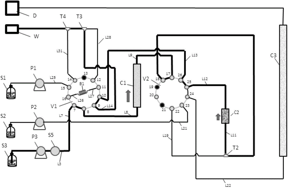
[0095] like Figure 13 As shown, a liquid chromatograph, on the basis of the liquid chromatograph described in Embodiment 2, also includes a post switch valve V5, and the post switch valve V5 has an interface m1, an interface n2, an interface x3, an interface y4, interface s5 and interface r6; a filter or a protector B2 is connected between the interface n2 and the interface s5; the interface y4 is connected to a section of the waste liquid flow channel L14, and the interface x3 is connected to the waste liquid flow channel L14 The other section of the first channel L3 is connected; the interface m1 is connected to one section of the first flow channel L3, and the interface r6 is connected to another section of the first flow channel L3.

[0096] Function description: The liquid chromatograph described in embodiment 3, except having all functions of embodiment 1 and 2, also has the following special functions:

[0097] 1. Filter or protector B2 interception function for ins...


PUM


Abstract

The invention provides a liquid chromatograph with an online cleaning function. The liquid chromatograph comprises a first runner (L3), a second runner (L21), an analysis runner (L22), a liquid waste runner, a cleaning runner (L25), a directional control valve (V1), a multi-runner changeover valve (V2) and the like. According to the liquid chromatograph, a liquid flow path is changed by changing the connected relation between two-position changeover valves; the online cleaning function of a first chromatographic column, an intermediate chromatographic column, a filter or a protector is respectively achieved; and online cleaning on the first chromatographic column and the intermediate chromatographic column can be simultaneously carried out.

Description

technical field [0001] The invention belongs to the field of liquid chromatography, and in particular relates to a liquid chromatography with an online cleaning function. Background technique [0002] The separation principle of liquid chromatography (Liquid Chromatography\LC) is to use the difference in the distribution coefficient, adsorption capacity and other affinity of various substances to be separated in the two phases to separate. A chromatographic pump is used to pass the mobile phase containing the sample through a stationary phase immiscible with the mobile phase immobilized in the chromatographic column. As the mixture carried in the mobile phase flows through the stationary phase, the components in the mixture interact with the stationary phase. Due to the differences in the nature and structure of each component in the mixture, the time for each component to be retained by the stationary phase is different, so that it flows out of the stationary phase in a ce...

Claims


Application Information

Patent Timeline
Patent Type & Authority Patents(China)
IPC IPC(8): G01N30/02
Inventor 王峰
Owner HUNAN DEMETER INSTR CO LTD
Why Eureka
Try Eureka