
FPGA (field programmable gate array)-based failure recovery method

A fault recovery and watchdog technology, applied in the direction of response errors, etc., can solve problems that affect FPGA programming, configuration, lack of configuration of the working status monitoring system, and failure to reset in time to achieve the effect of improving reliability

Active Publication Date: 2015-02-04
LUOYANG INST OF ELECTRO OPTICAL EQUIP OF AVIC
View PDF6 Cites 5 Cited by
  • Summary
  • Abstract
  • Description
  • Claims
  • Application Information

AI Technical Summary

Problems solved by technology

[0004] The existing FPGA is not equipped with a working status monitoring system. If an abnormal phenomenon occurs, it cannot be reset in time, and it also affects the programming and configuration of the FPGA.

Method used


Image

  • FPGA (field programmable gate array)-based failure recovery method
  • FPGA (field programmable gate array)-based failure recovery method
  • FPGA (field programmable gate array)-based failure recovery method

Examples


Embodiment Construction

[0018] The present invention will be further introduced below in conjunction with the accompanying drawings and specific embodiments.

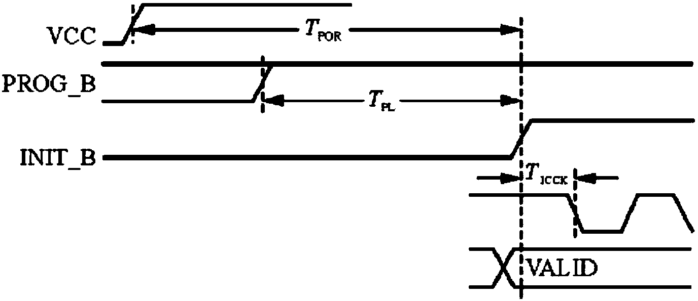
[0019] Such as figure 1 As shown, when the PROG_B signal of Xilinx FPGA is low, the configuration register is cleared, and the FPGA reloads the program from the configuration Flash.

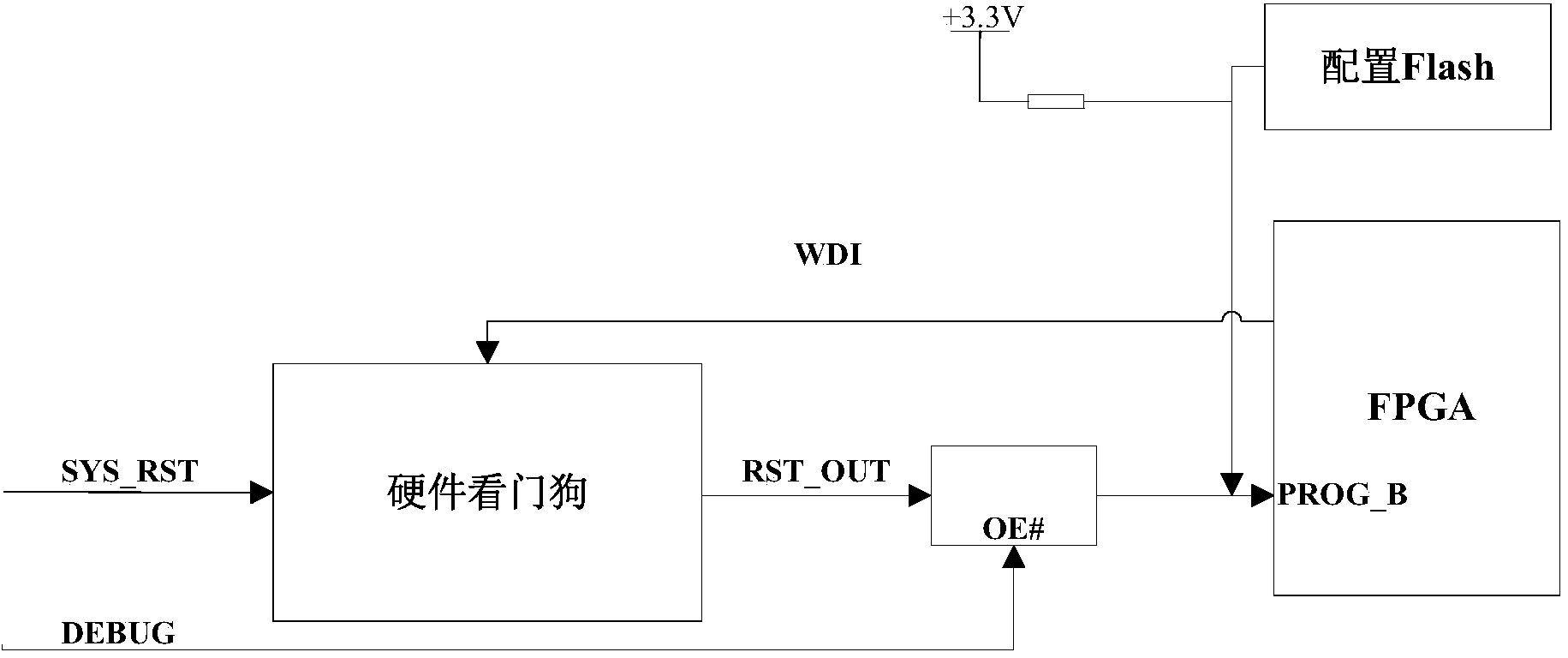
[0020] Such as figure 2 As shown, the fault recovery system is mainly composed of a hardware circuit unit and a logic watchdog unit. The hardware circuit unit mainly includes hardware watchdog chip, Xilinx FPGA and configuration Flash; the logic watchdog unit is mainly implemented by coding the logic written on the PC, and compiling and generating software or logic suitable for chip loading format. Configuration Flash and hardware watchdog are connected to PROG_B of Xilinx FPGA.

[0021] In addition, if the DEBUG signal is not connected, there will be a problem that the bit file cannot be burned during the debugging process, but the mcs file can be burned nor...


PUM


Abstract

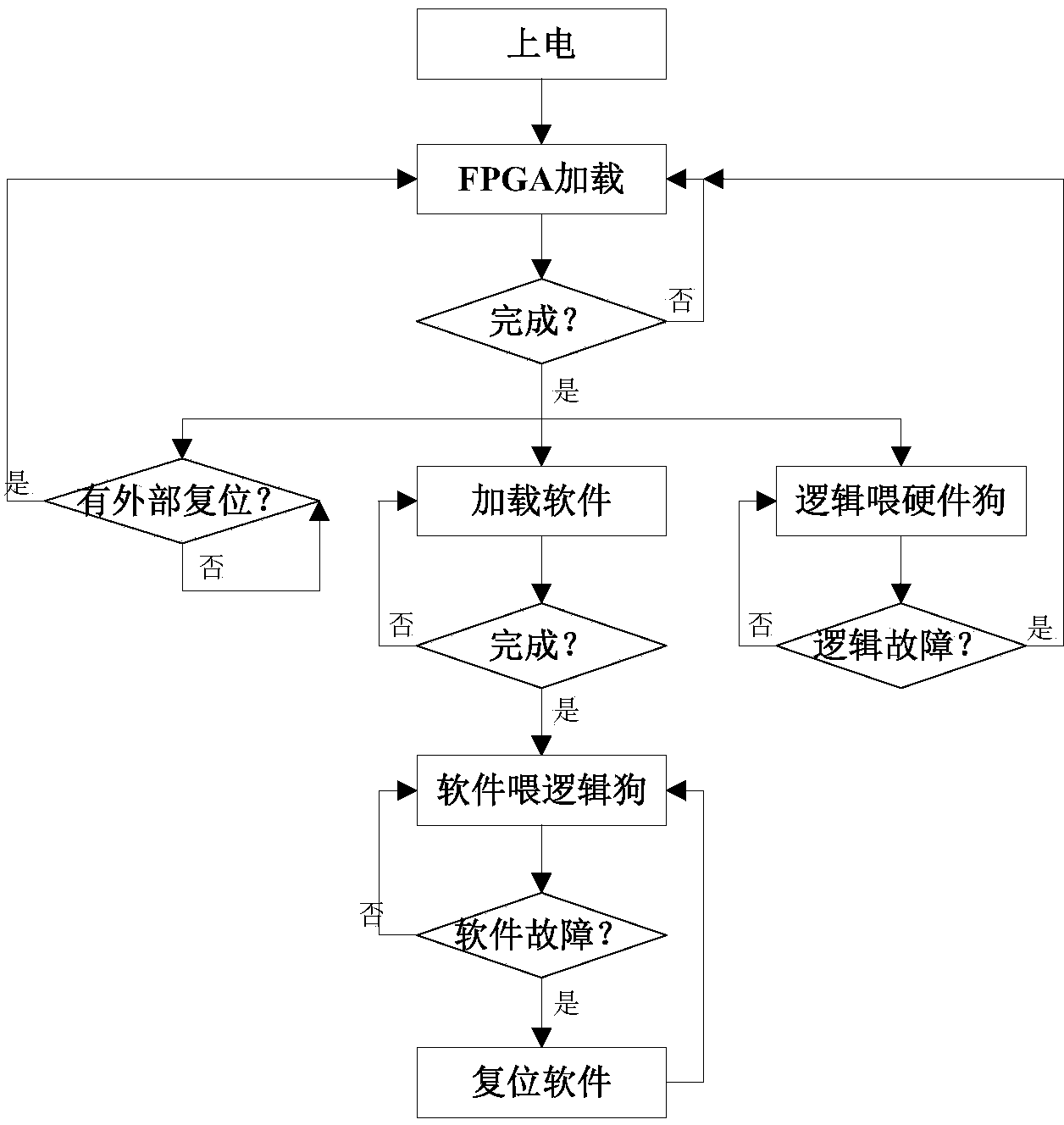
The invention discloses an FPGA (field programmable gate array)-based failure recovery method. The FPGA-based failure recovery method can be used for monitoring the working condition of an FPGA after power on; if the phenomenon that logic loading fails or breaks down and the like occurs, the logic is reset by a hardware watchdog; if software embedded into the FPGA is loaded unsuccessfully or breaks down, the software is reset through logic software so as to realize failure recovery of the module, and moreover, operations, such as burning and configuration, on the FPGA are not influenced. The method is suitable for the conditions that failure recovery is needed, so that the work reliability is improved; moreover, the method has a general function, and can be suitable for various Xilinx FPGA-based failure recovery conditions.

Description

technical field [0001] The invention relates to a fault recovery method based on FPGA. Background technique [0002] Xilinx's FPGA chip is a volatile device based on SRAM technology, and the circuit function is realized by data stored in SRAM configuration registers. After the FPGA chip is powered on, it must read the configuration information from the configuration FLASH before it can work normally. [0003] The FPGA configuration process includes 5 stages: initialization, clearing the configuration memory, loading configuration data, CRC check, START-UP, the power-on sequence of the configuration process is as follows figure 1 As shown, when the chip is powered on or the PROG_B signal of the FPGA is a low pulse, the configuration register will be cleared, that is, the configuration information will be read from the configuration FLASH again. The shortest pulse time of PROG_B is determined by T POR The time parameter determines that when the signal is valid (low level), ...

Claims


Application Information

Patent Timeline
Patent Type & Authority Applications(China)
IPC IPC(8): G06F11/07
Inventor 董欢徐恺
Owner LUOYANG INST OF ELECTRO OPTICAL EQUIP OF AVIC
Learn More