Axial force balancing structure of centrifugal closed impeller

A technology of centrifugal closed type and impeller shaft, which is applied in non-variable pumps, parts of pumping devices for elastic fluids, machines/engines, etc., which can solve the problem of impeller inlet flow and limited use of balance discs , complex processing and other issues

Active Publication Date: 2015-02-11
TSINGHUA UNIV
View PDF7 Cites 10 Cited by
  • Summary
  • Abstract
  • Description
  • Claims
  • Application Information

AI Technical Summary

Problems solved by technology

For example, the disadvantage of setting the balance hole is that it will affect the flow at the inlet of the impeller and reduce the efficiency of the impeller. It is not suitable for occasions with high impeller performance requirements; Complicated, not suitable for occasions with long shafts; the disadvantages of setting the balance plate are: 1) the length of the shaft is increased; 2) it is dangerous to the me

Method used


Image

  • Axial force balancing structure of centrifugal closed impeller

Examples


Embodiment Construction

[0014] The present invention will be further described in detail below in conjunction with the accompanying drawings and specific embodiments.

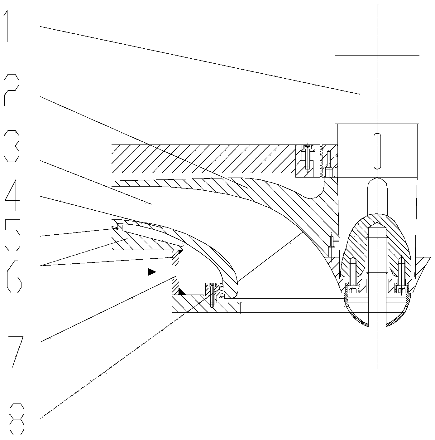
[0015] The axial force balance structure of the centrifugal closed impeller of the present invention is shown in the accompanying drawings. On the basis of the common centrifugal closed impeller structure, the following structure is added: between the impeller wheel cover 4 and the casing 6 near the outlet of the centrifugal closed impeller 3 Set the sealing ring 5, and set the casing inlet hole 7 on the casing 6 at the same time. The casing 6 is the casing part corresponding to the impeller wheel cover 4 here. The sealing ring 5 is arranged near the outlet of the centrifugal closed impeller 3, and the corresponding radius value is less than or equal to the outlet radius of the centrifugal closed impeller 3, so as to ensure that the external high-pressure medium introduced from the casing inlet hole 7 acts on the impeller cover 4, and...


PUM


Abstract

An axial force balancing structure of a centrifugal closed impeller comprises a sealing ring which is arranged between an impeller cover and a housing and near the outlet of the centrifugal closed impeller, an impeller inlet seal arranged near the inlet of the centrifugal closed impeller, and a housing inlet formed in the housing, wherein the impeller cover, the housing, the sealing ring and the impeller inlet seal form a cavity; a high pressure medium is introduced into the cavity from the outside through the housing inlet; the pressure of the high pressure medium is higher than the medium pressure at the outlet of the centrifugal closed impeller. The axial force balancing structure can balance an existing axial force from an impeller disc to the impeller cover of the centrifugal closed impeller; the axial force balancing structure does not affect flowing of the medium inside the centrifugal closed impeller, so that the efficiency of an impeller is not affected; the axial force balancing structure does not increase the axial length; the high pressure medium can be from the medium at an outlet of a pressure expander behind the centrifugal closed impeller, so that a risk of medium leakage is avoided; the axial force balancing structure is simple in structure and easy to implement.

Description

technical field [0001] The invention relates to the technical field of impeller mechanical engineering, in particular to an axial force balance structure of a centrifugal closed impeller. Background technique [0002] For centrifugal pumps, fans and compressors, due to the different fluid forces on the outside of the impeller disc and the wheel cover, there is still a part of the axial force after canceling each other. This part of the axial force acts on the impeller, and because the impeller Arranged on the shaft, so that the axial force also acts on the rotor, and its direction of action is from the high pressure end to the low pressure end. It is necessary to try to balance or eliminate the axial force on the rotor, otherwise it will cause the rotor to move and even contact the fixed parts, causing damage to the parts. In most cases, it is not enough to rely on the thrust bearing alone, and a hydraulic / pneumatic balancing method is required to balance part of the axial ...

Claims


Application Information

Patent Timeline
IPC IPC(8): F04D29/66F04D29/08
CPCF04D29/0516F04D29/284F04D29/669F04D29/086
Inventor 王宏张勤昭张作义吴宗鑫
Owner TSINGHUA UNIV
Why Eureka
Try Eureka