Eureka AIR delivers breakthrough ideas for toughest innovation challenges, trusted by R&D personnel around the world.

an expansion valve

The technology of an expansion valve and a valve cavity is applied in the field of an expansion valve for automobile air conditioners, which can solve the problems of capillary damage, easy rupture of the capillary, and failure of the expansion valve to work normally, and achieves the effect of ensuring the reliability of vibration.

Active Publication Date: 2018-01-26
DUNAN ENVIRONMENT TECH
View PDF9 Cites 0 Cited by
  • Summary
  • Abstract
  • Description
  • Claims
  • Application Information

AI Technical Summary

Problems solved by technology

[0002] In the existing expansion valve, the pilot valve and the main valve are often connected by a capillary tube, and the capillary tube is connected to the valve body by welding or other means. In the actual use environment of the expansion valve, such as in a car, there will inevitably be vibrations, causing the capillary tube to The joints are prone to breakage, and since the capillary is an external tubular part, it is a weak link in the expansion valve as a whole. Damage to the capillary will cause the entire expansion valve to fail to work normally, and the capillary is damaged, often need to replace the entire expansion valve

Method used


Image

  • an expansion valve
  • an expansion valve
  • an expansion valve

Examples


Embodiment 1

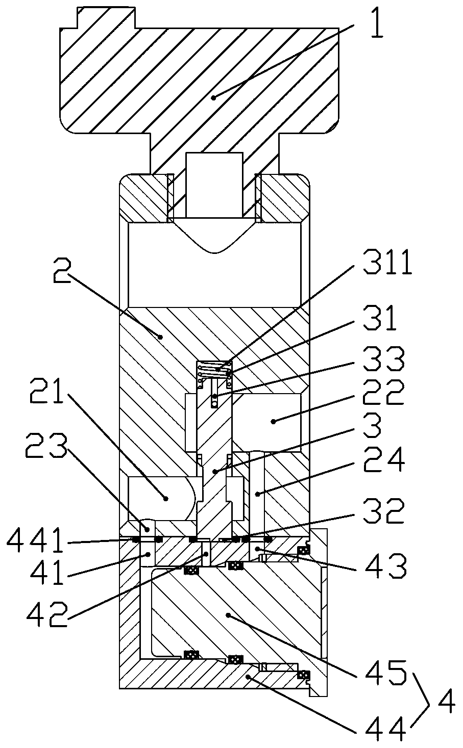
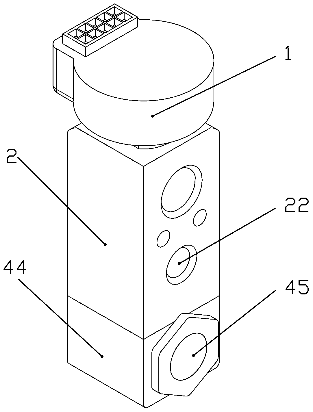
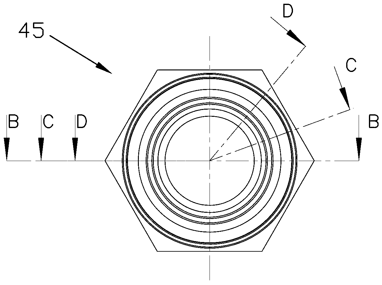
[0033] refer to Figure 1 to Figure 7 , an expansion valve, comprising a main valve body 2, a valve cavity is arranged in the main valve body 2, a main inlet 21 and a main outlet 22 are opened in the valve cavity, a valve core 3 is housed in the valve cavity, and the valve core 3 divides the valve cavity into The upper cavity 31 and the lower cavity 32 are not communicated with each other. The upper cavity 31 is provided with a spring 311 to push the valve core 33 downward. The upper end of the valve core 3 has a pressure relief hole 33 communicating with the main outlet 22. A pilot valve 4 is provided with a microvalve 5 on the pilot valve. The pilot valve 4 is provided with a branch inlet 41, a pilot valve port 42 and a branch outlet 43. The branch inlet 41 communicates with the main inlet 21, and the pilot valve port 42 communicates with the lower chamber 32. , the branch outlet 43 communicates with the main outlet 22 , and the microvalve 5 controls the pilot valve port 42 ...

Embodiment 2

[0049] The difference of this embodiment is that the expansion valve is a normally closed valve, and when the third microvalve plate is not energized, the flow channel window is connected to the outlet and the orifice; when the third microvalve plate is energized, the flow channel window is connected to the inlet and Orifice, you can change the layout of the inlet, orifice and outlet or change the position of the flow channel window according to the needs. When the flow channel window is connected to the outlet and the orifice, and when the flow channel window is connected to the inlet and the orifice, the flow of refrigerant Flow direction is consistent with embodiment one.


PUM


Abstract

The invention discloses an expansion valve, which comprises a main valve body, a valve cavity is arranged in the main valve body, a main inlet and a main outlet are opened in the valve cavity, a valve core is installed in the valve cavity, and the valve core divides the valve cavity into mutually unconnected parts. The upper chamber and the lower chamber, the upper chamber is equipped with a spring to push the valve core downward, the upper end of the valve core is opened with a pressure relief hole connected with the main outlet, and the main valve body is also equipped with a pilot valve, which includes a pilot valve body, a pilot The valve head and the pilot valve body are connected with the main valve body, and a microvalve is installed on the pilot valve head, and the microvalve controls the opening and closing of the main valve. The opening degree of the expansion valve can be adjusted at will through micro-valve control, which solves the technical problem in the prior art that the expansion valve can only adjust the opening degree of the valve port through the temperature sensed by the temperature sensing package. The embodiment of the invention is used in the field of expansion valves.

Description

【Technical field】 [0001] The invention relates to an expansion valve, in particular to an expansion valve for an automobile air conditioner. 【Background technique】 [0002] In the existing expansion valve, the pilot valve and the main valve are often connected by a capillary tube, and the capillary tube is connected to the valve body by welding or other methods. In the actual use environment of the expansion valve, such as in a car, there will inevitably be vibrations, causing the capillary tube to The joints are prone to breakage, and since the capillary is an external tubular part, it is a weak link in the expansion valve as a whole. Damage to the capillary will cause the entire expansion valve to fail to work normally, and the capillary is damaged, often need to replace the entire expansion valve . 【Content of invention】 [0003] The problem to be solved by the present invention is to provide a silicon expansion valve that can accurately control the refrigerant flow ra...

Claims


Application Information

Patent Timeline
Patent Type & Authority Patents(China)
IPC IPC(8): F25B41/06F25B41/31
CPCF25B2341/067F25B2341/068F25B2341/06F25B41/31
Inventor 王鑫楠段飞刘正
Owner DUNAN ENVIRONMENT TECH
Why Eureka
Eureka Blog
Learn More