Eureka AIR delivers breakthrough ideas for toughest innovation challenges, trusted by R&D personnel around the world.

micro speaker

A technology of micro-speakers and components, applied in the direction of electrostatic transducer speakers, sensors, electrostatic sensors, etc., can solve the problems of low service life, low vibration reliability of piston connecting rod components, poor acoustic performance, etc.

Active Publication Date: 2021-04-20
AAC TECH PTE LTD
View PDF14 Cites 0 Cited by
  • Summary
  • Abstract
  • Description
  • Claims
  • Application Information

AI Technical Summary

Problems solved by technology

[0004] However, in the related art, due to the lack of guiding and balancing devices during the vibration process, the connecting rod is easily affected by the stress distribution of the driving device, signal input, etc., and deviates from the stroke and tilts towards the substrate, especially in the high frequency range, the situation will be further improved. deterioration
The vibration reliability of the piston connecting rod assembly is low and the acoustic performance is poor. In severe cases, the connecting rod breaks and the entire speaker is damaged and cannot produce sound, and the service life is low

Method used


Image

  • micro speaker
  • micro speaker
  • micro speaker

Examples


Embodiment approach 1

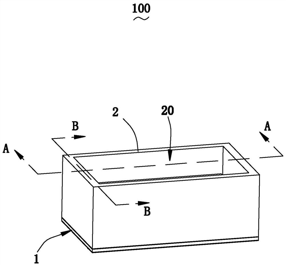
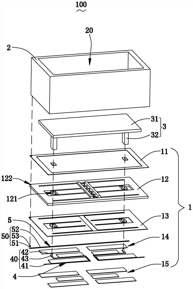
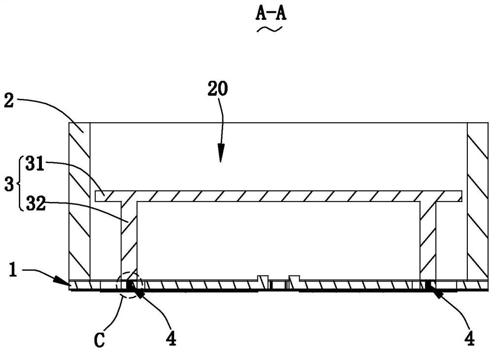
[0039] Please also see Figure 1-7 As shown, the present invention provides a micro-speaker 100 , which includes a driving device 1 , a substrate 2 , a piston rod assembly 3 , a first charge injection device 4 and a second charge injection device 5 .

[0040] The driving device 1 is used to fixedly support the substrate 2 and the piston connecting rod assembly 3 , and the driving device 1 is used to drive the piston connecting rod assembly 3 to vibrate and sound along the thickness direction of the substrate 2 . It is worth mentioning that the driving device 1 is insulated from the piston connecting rod assembly 3 and the substrate 2 respectively.

[0041] It is worth mentioning that the driving method of the driving device 1 includes but not limited to any one of piezoelectric driving, electrostatic driving and electromagnetic driving.

[0042] For example, in this embodiment, the drive device 1 adopts a piezoelectric drive, and more specifically, the drive device 1 includes...

Embodiment approach 2

[0059] see Figure 8 As shown, the microspeaker 100a of the second embodiment is basically the same as the microspeaker of the first embodiment. The structure of the injection device is different. In the microspeaker 100a of the second embodiment, the piezoelectric driver on the piston rod assembly and its peripheral control circuit are used to replace the first charge channel for injecting charge into the piston rod assembly. The following will combine The specific structure is explained:

[0060] The microspeaker 100a includes a driving device 1a, a substrate 2a, a piston rod assembly 3a, a first charge injection device 4a, and a second charge injection device 5a.

[0061] The driving device 1a fixedly supports the piston connecting rod assembly 3a and the substrate 2a, and the driving device 1a is insulated from the piston connecting rod assembly 3a and the substrate 2a respectively, and the driving device 1a uses To drive the piston rod assembly 3a to vibrate and make so...


PUM


Abstract

The invention provides a micro-speaker, which includes a substrate, a piston connecting rod assembly, a driving device, a first charge injection device and a second charge injection device; the substrate penetrates along its thickness direction to form a receiving cavity; In the housing chamber, the piston connecting rod assembly is spaced apart from the substrate and is insulated from the substrate; the driving device fixedly supports the piston connecting rod assembly and the substrate, and the driving device is respectively insulated from the piston connecting rod assembly and the substrate. Drive the piston connecting rod assembly to vibrate along the thickness direction of the substrate; the first charge injection device is connected to the piston connecting rod assembly to inject charges into the piston connecting rod assembly; the second charge injection device is connected to the substrate to inject charges into the substrate Charges are injected; the electric polarity of the charge of the substrate is the same as that of the charge of the piston connecting rod assembly, so that electrostatic repulsion is generated between the substrate and the piston connecting rod assembly. Compared with related technologies, the micro-speaker of the invention has high reliability, long service life and excellent acoustic performance.

Description

【Technical field】 [0001] The invention relates to the technical field of an electroacoustic conversion device, in particular to a micro speaker. 【Background technique】 [0002] With the advent of the mobile Internet era, the number of smart mobile devices continues to rise. Among the many mobile devices, the mobile phone is undoubtedly the most common and portable mobile terminal device. At present, the functions of mobile phones are extremely diverse, one of which is the function of high-quality music. Therefore, micro-speakers for playing sound are widely used in current smart mobile devices. [0003] A microspeaker in the related art includes a driving device, a substrate having a receiving cavity and fixedly supported on the driving device, and a piston rod assembly fixedly supported on the driving device and arranged at a distance from the substrate, and the driving device drives The piston connecting rod assembly vibrates along the thickness direction of the substrat...

Claims


Application Information

Patent Timeline
Patent Type & Authority Patents(China)
IPC IPC(8): H04R19/00H04R19/02
CPCH04R19/005H04R19/02
Inventor 程诗阳朱国但强李杨
Owner AAC TECH PTE LTD
Why Eureka
Eureka Blog
Learn More