A working method of a frequency-encoded fiber optic time-domain reflectometer

A working method and frequency coding technology, applied in the direction of testing optical performance, etc., can solve the problems of shortening the measurement distance, reducing the energy of the optical pulse, and the parameters cannot be realized at the same time, achieving short duration, maintaining spatial resolution, and achieving spatial resolution. rate and the effect of long detection distances

Active Publication Date: 2017-02-15
宁波联河光子技术有限公司
View PDF6 Cites 0 Cited by
  • Summary
  • Abstract
  • Description
  • Claims
  • Application Information

AI Technical Summary

Problems solved by technology

[0003] In the existing OTDR technology, the detection distance and spatial resolution are a pair of contradictions that restrict each other. In order to achieve high spatial resolution, it is necessary to reduce the duration of the pulse, which reduces the energy of the optical pulse, resulting in a shortened measurement distance.
The existing OTDR technology has respectively achieved a detection distance of thousands of kilometers and a spatial resolution of 1 meter, but these two parameters cannot be realized at the same time

Method used


Image

  • A working method of a frequency-encoded fiber optic time-domain reflectometer
  • A working method of a frequency-encoded fiber optic time-domain reflectometer
  • A working method of a frequency-encoded fiber optic time-domain reflectometer

Examples


Embodiment Construction

[0028] The preferred embodiments of the present invention will be described below in conjunction with the accompanying drawings. It should be understood that the preferred embodiments described here are only used to illustrate and explain the present invention, and are not intended to limit the present invention.

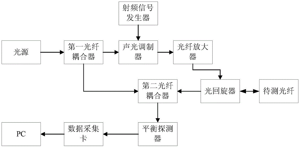
[0029] Such as figure 1 As shown, a frequency-encoded optical fiber time domain reflectometer includes a light source, a first optical fiber coupler (CP1), an acousto-optic modulator (AOM), a radio frequency signal generator (RFSG), an optical fiber amplifier (EDFA), and an optical gyrator (CIR), the second optical fiber coupler, balanced detector (BPD) and data acquisition card, the light emitted from the light source is divided into two beams after passing through the first coupler, and one beam of light passes through the acousto-optic modulator and becomes Frequency-coded pulse signal, then the pulse signal is used as the detection pulse signal after passing thr...


PUM


Abstract

The invention discloses a frequency code optical fiber time domain reflectometer and a working method thereof. The frequency code optical fiber time domain reflectometer comprises a light source, a first optical fiber coupler, an acoustic optical modulator, a radio frequency signal generator, an optical fiber amplifier, an optical gyroscope, a second optical fiber coupler, a balance detector and a data acquisition card. Optical pulses are subjected to frequency modulation so that the space resolution ratio is not limited by optical pulse lasting time and the space resolution ratio does not depend on the width of the pulse, but depends on a frequency modulation range of detection pulses, so that the aims of high space resolution ratio and long detection distance are realized simultaneously.

Description

technical field [0001] The invention relates to the field of optical fiber transmission measurement, in particular to a working method of a frequency coded optical fiber time domain reflectometer. Background technique [0002] OTDR (Coherent Optic Time Domain Reflectometry) is a measuring instrument for measuring the transmission characteristics of optical fibers. It has been widely used in optical fiber communication systems. It uses signals such as back Rayleigh scattered light of optical fibers to measure the attenuation, properties such as loss and reflection. As a non-destructive optical fiber measurement technology, OTDR can measure the attenuation of the entire optical fiber link and provide length-related attenuation details, specifically for detecting, locating and measuring events anywhere on the optical fiber link. [0003] In the existing OTDR technology, the detection distance and spatial resolution are a pair of contradictions that restrict each other. In orde...

Claims


Application Information

Patent Timeline
Patent Type & Authority Patents(China)
IPC IPC(8): G01M11/02
Inventor 何祖源刘庆文樊昕昱杜江兵马麟
Owner 宁波联河光子技术有限公司
Why Eureka
Try Eureka