

Narrow-frame touch screen
A technology of touch screen and narrow frame, which is applied in the direction of instruments, electrical digital data processing, and data processing input/output process. Good conductivity, reduced frame width, sensitive touch effect
- Summary
- Abstract
- Description
- Claims
- Application Information
AI Technical Summary
Problems solved by technology
Method used
Image

Examples
Embodiment 1
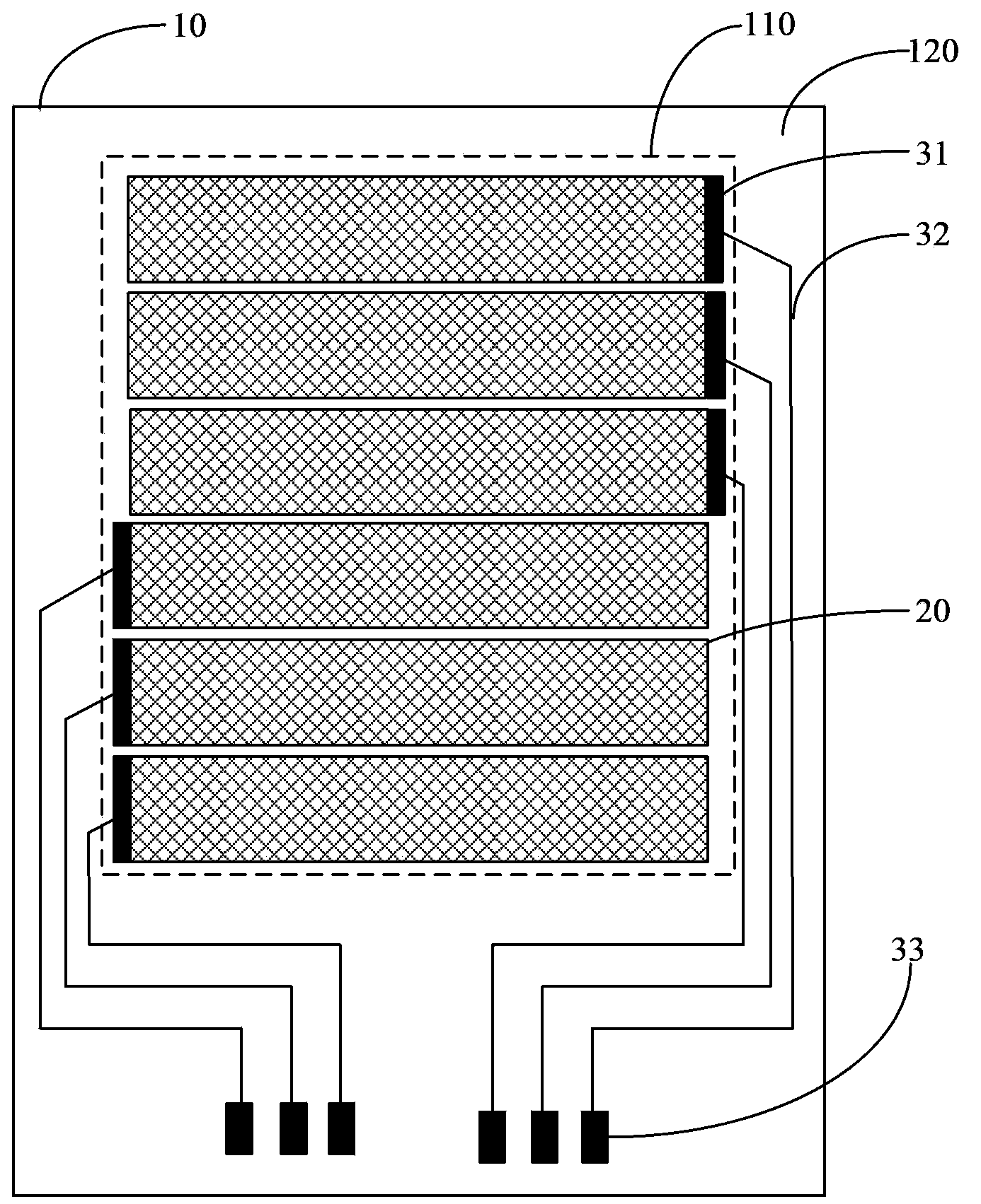
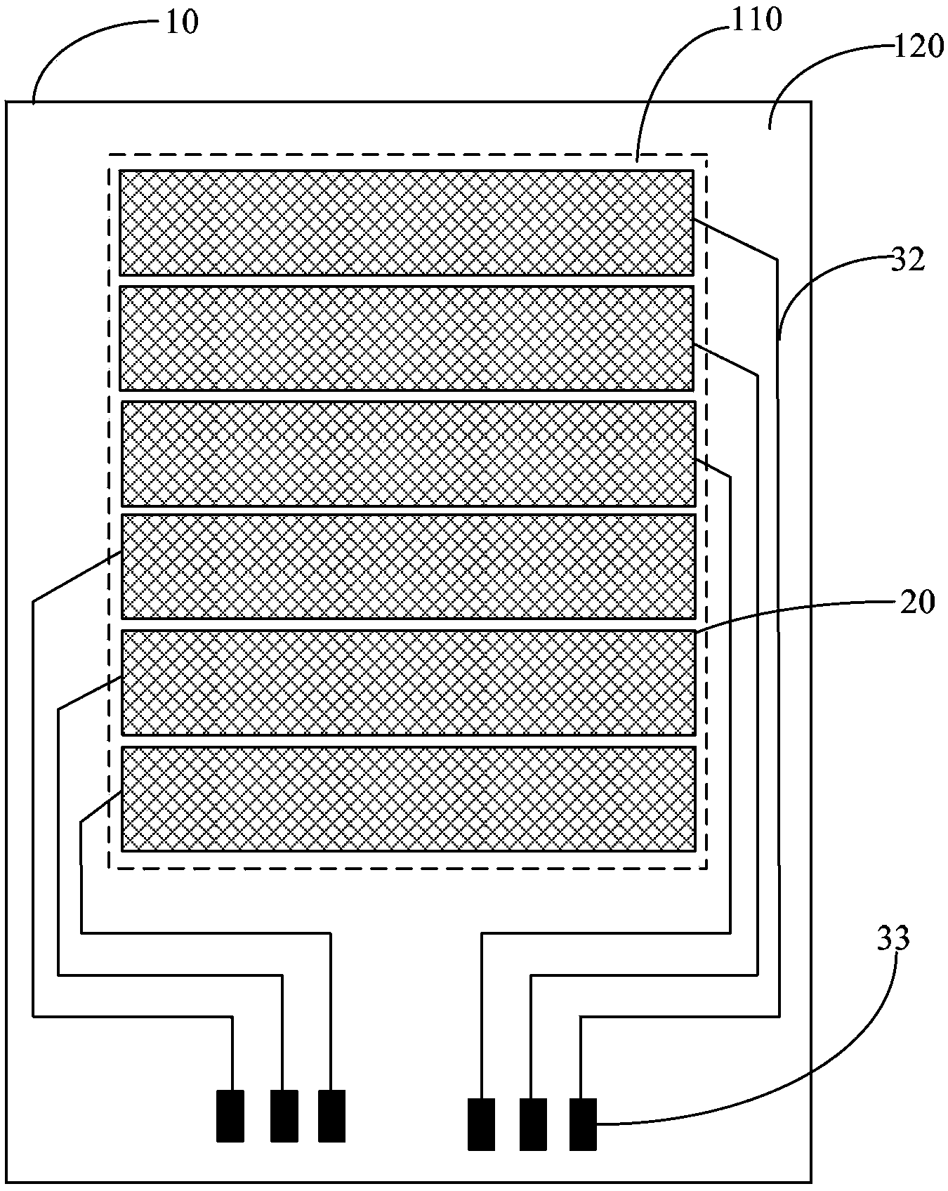
[0038] figure 2 It is a schematic structural diagram of a narrow-frame touch screen provided in Embodiment 1 of the present invention. The narrow frame touch screen of this embodiment includes a substrate 10 , a conductive layer 20 and lead electrodes. The surface of the base 10 can be divided into a visible touch area 110 and an invisible frame area 120 , and the conductive layer 20 is arranged in the touch area 110 of the base 10 . The improvement of the touch screen in this embodiment is that the lead electrodes include electrically connected electrode wires 32 and external terminals 33, which are arranged in the frame area 120 of the substrate 10, and the electrode wires 32 are connected to the grid-shaped conductive layer 20. The edge is electrically connected.
[0039] In the narrow-frame touch screen provided in this embodiment, the pattern of the conductive layer 20 can be arranged in multiple rows or columns as required, and the conductive layer 20 of each pattern ...
Embodiment 2
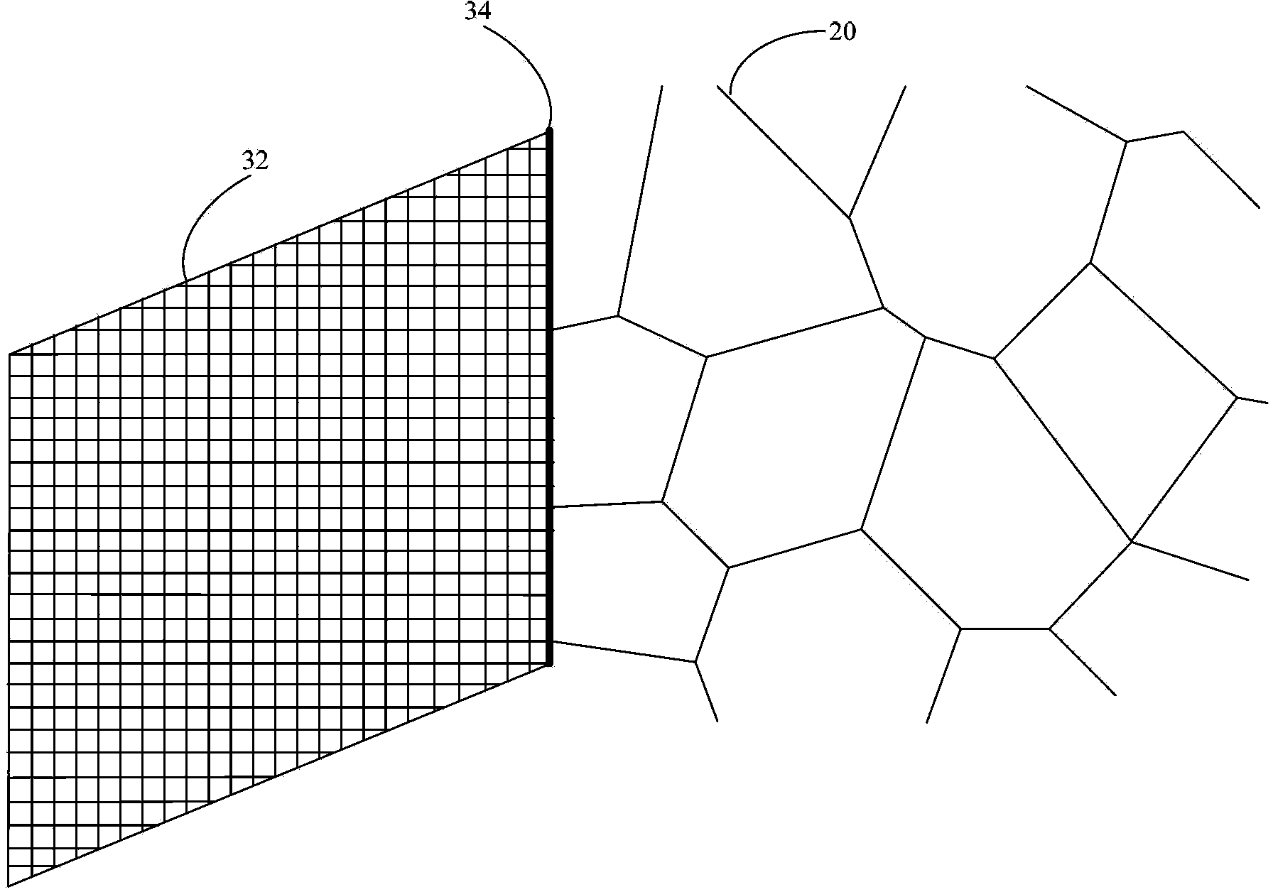
[0047] image 3 The partial structural diagram of the narrow frame touch screen provided by Embodiment 2 of the present invention, this embodiment is based on the above Embodiment 1, and further includes a first connection line 34 connected between the conductive layer 20 and the electrode line 32, The first connection line 34 is connected to each grid line of the conductive layer 20 at the edge of the conductive layer 20, and the first connection line 34 is connected to each grid line of the electrode line 32 at the edge of the electrode line 32. line connected.
[0048] In this embodiment, in the form of setting connection lines, it is ensured that the wires of each grid can be connected to the first connection line 34 at the edges of the two grids, so as to realize the multi-point connection between the grid-shaped conductive layer 20 and the electrode lines 32. Electrical connection, improve electrical conductivity.
[0049] The first connection line 34 can be formed by ...
Embodiment 3
[0051] Figure 4 The partial structural diagram of the narrow frame touch screen provided by Embodiment 3 of the present invention. This embodiment is based on the above Embodiment 1, and is further provided with a transition section 35. The transition section 35 is a grid-like line located on the frame The region 120 is connected between the conductive layer 20 and the electrode lines 32 , and the grid density of the transition section 35 is greater than or equal to the grid density of the conductive layer 20 .
[0052] The transition section 35 in this embodiment can be regarded as extending from the edge of the grid of the conductive layer 20. Since there is usually a certain gap between the grid density of the conductive layer 20 and the grid density of the electrode lines 32, the grid lines The number of connection points between them is reduced, so a transition section 35 with a grid density between the two can be provided. The transition section 35 can be directly conn...
PUM
 Abstract
Description
Claims
Application Information