Improved thin power inductor manufacturing process

A thin technology of power inductors, applied in the manufacture of inductors/transformers/magnets, circuits, coils, etc., can solve problems such as high manufacturing costs, inability to apply production lines, and complicated manufacturing processes

Active Publication Date: 2015-02-11
INPAQ TECH
View PDF6 Cites 6 Cited by
  • Summary
  • Abstract
  • Description
  • Claims
  • Application Information

AI Technical Summary

Problems solved by technology

[0006] However, in the U.S. Patent No. 7,176,773B2, although the manufacturing steps can produce inductors that meet the miniaturization requirements of electrical products, the manufacturing process is too complicated and the manufacturing cost is high, so it cannot be applied to the actual production line.

Method used


Image

  • Improved thin power inductor manufacturing process
  • Improved thin power inductor manufacturing process
  • Improved thin power inductor manufacturing process

Examples


Embodiment Construction

[0051] The manufacturing process of the improved thin power inductor of the present invention comprises:

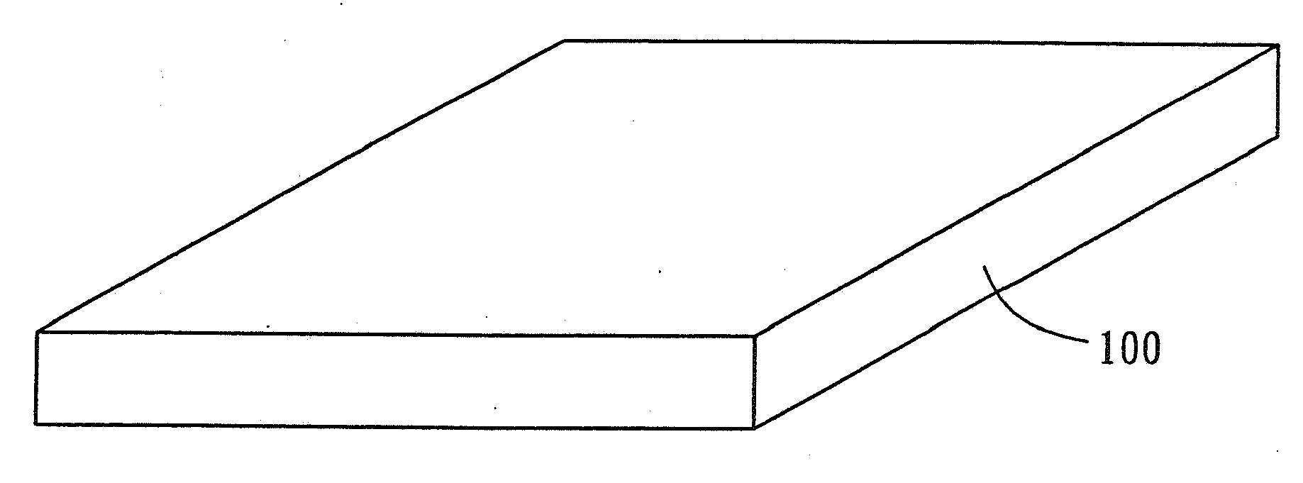
[0052] Substrate processing step: use chemical solvents such as methanol or acetone to remove impurities and grease on the surface of the substrate 100, then remove oxides on the surface of the substrate with hydrofluoric acid, and then dehydrate the substrate 100 (Dehydration Bake) (such as figure 1 shown);

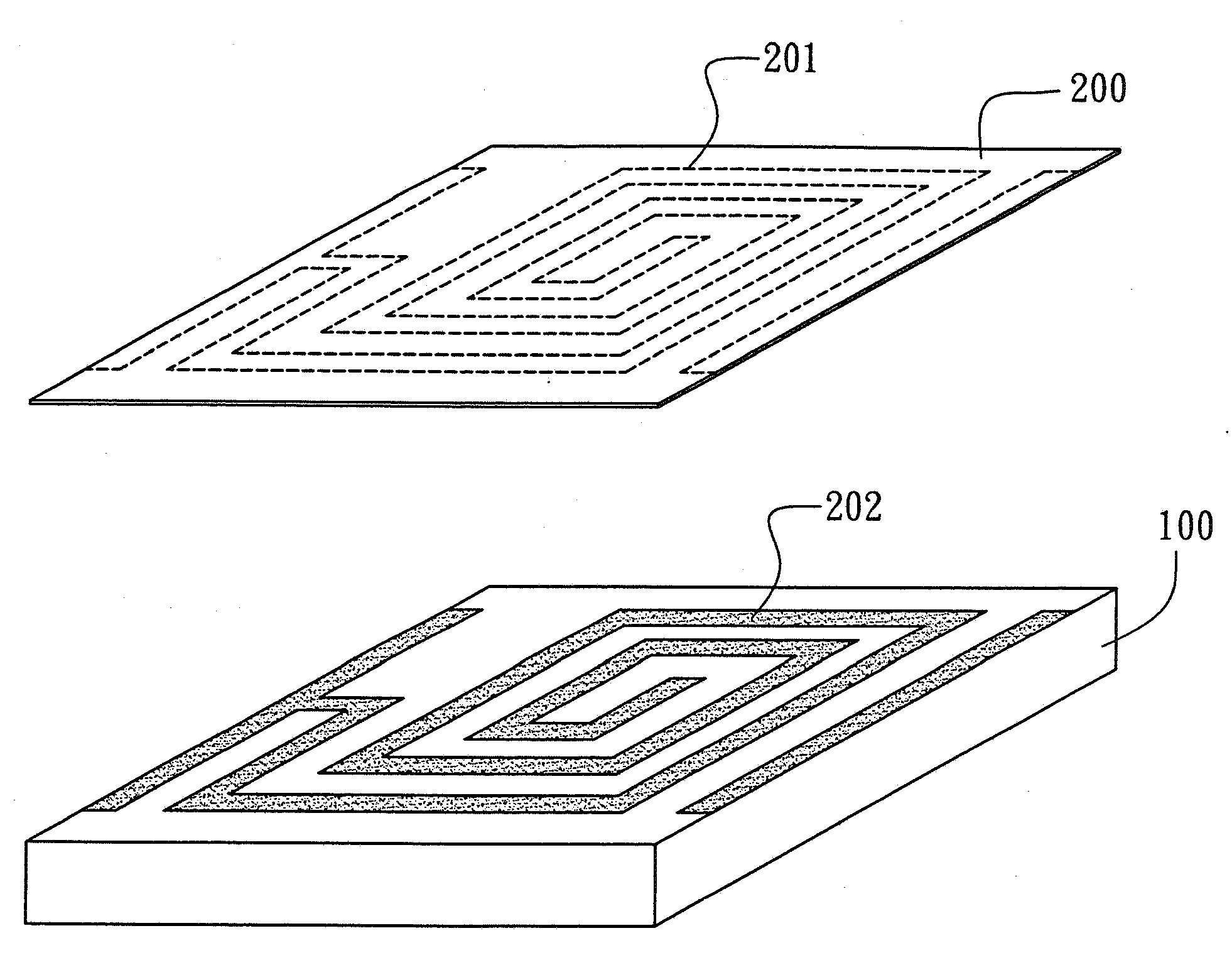
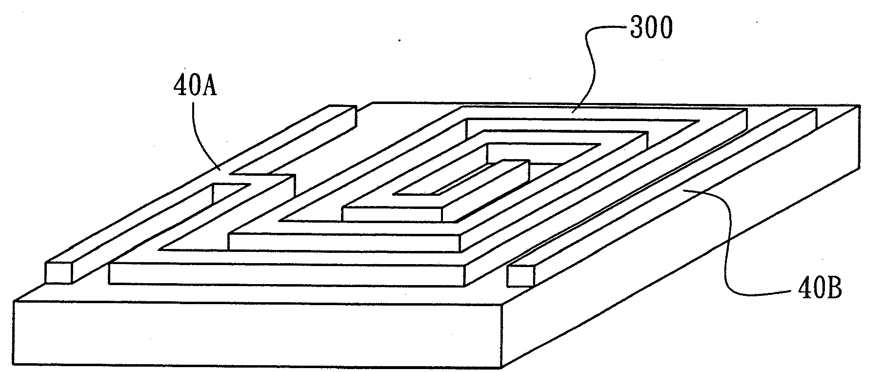
[0053] The step of forming the spiral inductance coil is to place a metal shield 200 with a spiral inductance pattern 201 on the surface above the substrate 100, and to form the spiral inductance coil on the upper surface of the substrate 100 by using a sputtering process and a copper electroplating process Seed layer 202 (such as figure 2 Shown); form the base layer spiral inductance coil 300 and side electrodes 40A, 40B again, and one end of the base layer spiral inductance coil 300 is connected with one side electrode 40A wherein (as image 3 shown);

[0054]...


PUM


Abstract

An improved thin power inductor manufacturing process comprises the steps of forming a spiral inductance coil through metal mask, a sputtering process and a copper electroplating process on a base plate; then printing an adhesive configured for a magnetic material on the outside of the spiral inductance coil so as to form an insulation coating layer and accordingly form a single-layer power inductor; sequentially manufacturing multiple-layer power inductors above the single-layer power inductor and enabling the multiple-layer power inductors to be mutually communicated when repeating the steps and accordingly forming a continuous spiral inductance coil.

Description

technical field [0001] The present invention relates to an improved manufacturing process of thin power inductors, especially refers to the helical inductance coil of the power inductance, which is shielded with metal, and is made in conjunction with the sputtering process and copper electroplating process, and the outer surface of the formed spiral inductance coil is passed through The colloid of the magnetic material configuration is printed to form an insulating coating layer. Background technique [0002] Existing power inductors are formed by using wires with a rectangular or circular cross-section and winding them into a helical inductance coil. The helical inductance coil has a plurality of coils extending in layers along the vertical direction, and its two ends are respectively connected with wires to connect with external electrodes. When making, put the helical wire that has been welded into the mold first, inject magnetic powder material into the mold, press the ...

Claims


Application Information

Patent Timeline
Patent Type & Authority Applications(China)
IPC IPC(8): H01F41/00H01F41/04H01F41/12
Inventor 叶秀伦张育嘉刘泽钧许秀美
Owner INPAQ TECH
Why Eureka
Try Eureka