An ultra-high-speed mechanical switch

A mechanical switch, ultra-high-speed technology, applied in the direction of air switch components, etc., can solve the problems of limited buffering, inability to meet the buffer requirements of ultra-high-speed mechanical switches, damage to the operating mechanism, etc. The effect of conversion efficiency

Active Publication Date: 2017-07-21
PINGGAO GRP +2
View PDF6 Cites 0 Cited by
  • Summary
  • Abstract
  • Description
  • Claims
  • Application Information

AI Technical Summary

Problems solved by technology

When this permanent magnet operating mechanism moves the moving iron core, there is a gap between the moving iron core and the inner wall of the gas chamber. The cushioning of the core is limited, which cannot meet the cushioning requirements of ultra-high-speed mechanical switches, and it is easy to damage the operating mechanism due to mechanical shock due to buffer failure

Method used


Image

  • An ultra-high-speed mechanical switch
  • An ultra-high-speed mechanical switch
  • An ultra-high-speed mechanical switch

Examples


Embodiment Construction

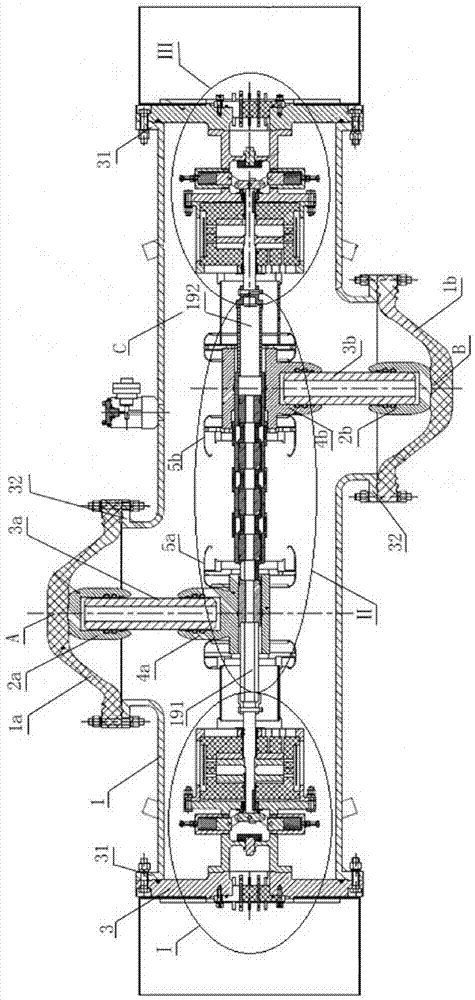
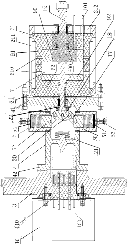
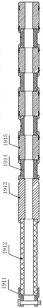
[0030] An embodiment of an ultra-high-speed mechanical switch of the present invention: as Figure 1-6 As shown, it includes a sealed insulating cylinder 1, and the inner space C of the insulating cylinder 1 is filled with high-pressure sulfur hexafluoride gas. and III, the repulsion operating mechanisms I and III are respectively driven and connected with switch pull rods 191 and 192 extending along the axial direction of the insulating cylinder 1, and the two ends of the switch pull rods 191 and 192 are respectively provided with breaking contacts, and the insulating cylinder The outer peripheral wall of the body 1 is respectively sealed and connected with a first conductive end A and a second conductive end B. The first conductive end A and the second conductive end B are located in the same plane passing through the axis of the insulating cylinder and are respectively arranged on the insulating cylinder. 1, the first conductive end A and the second conductive end B are ele...


PUM


Abstract

An ultra-high-speed mechanical switch comprises an insulation casing (1) that is internally provided with an electromagnetic operating mechanism used for driving switch pull rods (191, 192) to perform switch-opening and switch-closing movements. The electromagnetic operating mechanism comprises a movable iron core (90) in transmission connection with the switch pull rods, and a sealed cavity through which the movable iron core moves in a reciprocating manner to implement switch-opening and switch-closing. When moving to either end of the sealed cavity, the movable iron core is respectively at a switch-closed position and a switch-opened position. The movable iron core is a moving plate that divides the sealed cavity into two portions. Through holes (610) that connect the inside and the outside of the sealed cavity and are used for feeding or discharging buffering media are formed at a switch-opening position and a switch-closing position or at positions close to said opening position and said closing position on a circumferential wall of the sealed cavity. By means of the ultra-high-speed mechanical switch, the switch pull rods can be effectively buffered in the opening and closing movements, and mechanical impact is avoided.

Description

technical field [0001] The invention relates to an ultra-high-speed mechanical switch for a DC circuit breaker. Background technique [0002] Multi-terminal DC transmission based on flexible DC transmission technology has been increasingly used in Europe, North America, China and other countries and regions. Although several multi-terminal DC transmission systems have been put into operation in the world, due to the lack of DC circuit breakers. The reliability, flexibility, and continuity of multi-terminal HVDC transmission are greatly restricted, which poses serious obstacles to its popularization and application, and also has a great impact on the construction of future DC grids. The lack of high-voltage DC circuit breakers has become a bottleneck problem affecting the construction of future DC power grids in the world, and its development is imminent. [0003] At present, when the flexible DC and multi-terminal DC transmission systems fail, a large short-circuit current ...

Claims


Application Information

Patent Timeline
Patent Type & Authority Patents(China)
IPC IPC(8): H01H31/02
CPCH01H31/02
Inventor 程铁汉张友鹏马志华胡延涛孙珂珂门博赵晓民刘畅
Owner PINGGAO GRP
Why Eureka
Try Eureka