Control channel transmission method, transmission processing method, communication node and terminal
A technology for control channels and communication nodes, which is applied in machine-to-machine/machine-type communication services, transmission systems, wireless communication, etc., and can solve the problem of not supporting repeated transmission of multiple subframes.
- Summary
- Abstract
- Description
- Claims
- Application Information
AI Technical Summary
Problems solved by technology
Method used
Image
Examples
Embodiment 1
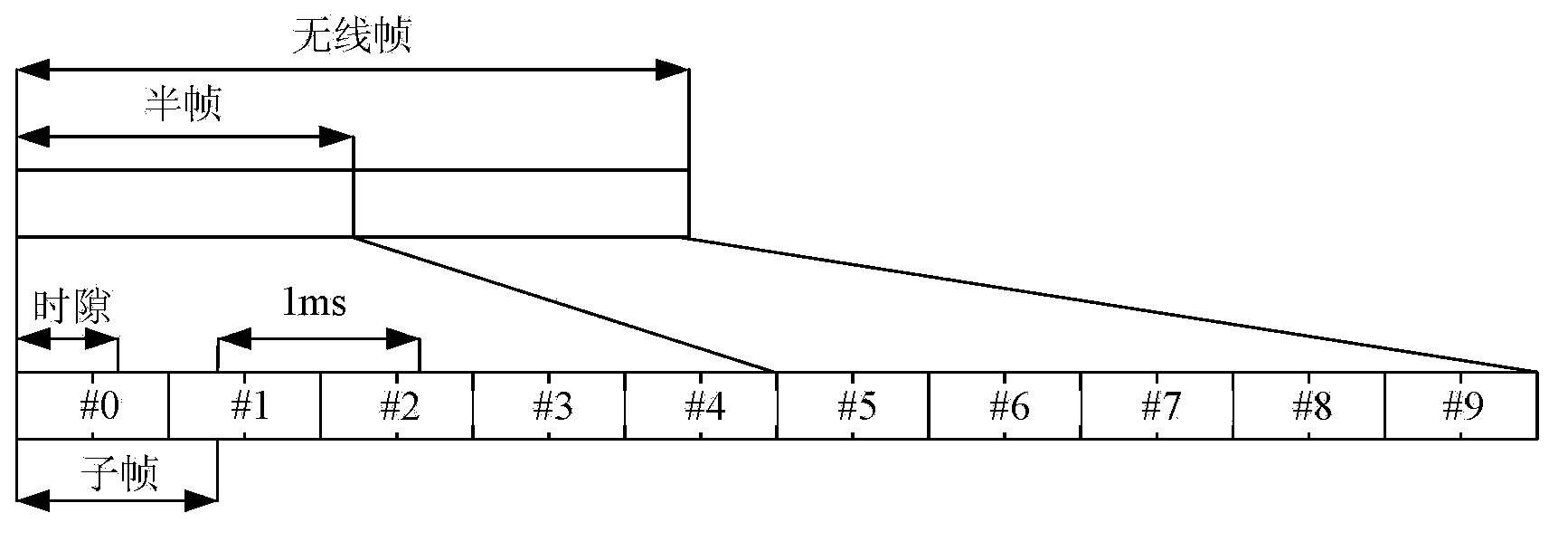
[0296] This embodiment will describe in detail the control channel transmission method provided by the present invention in an FDD (Frequency Division Duplexing, Frequency Division Duplexing) system.
[0297] The specific processing steps on the base station side are as follows Figure 8 Shown, including:
[0298] In step 801, the base station sends a system message, and at the same time uses the control channel to schedule and instruct the traffic channel carrying the system message for transmission. The fixed starting subframe position satisfies the relational expression (k+h*n) mod N=0, where k represents the number of the starting subframe available downlink subframe in the radio frame, 0≤k≤h-1, n means starting The radio frame where the initial subframe k is located, h is the number of available downlink subframes included in a radio frame, and N represents the number of repeated transmissions of the control channel. At this time, h=10 and k=0. At this time, all subframes ca...
Embodiment 2
[0305] This embodiment will describe in detail the control channel transmission method provided by the present invention in an FDD (Frequency Division Duplexing, Frequency Division Duplexing) system.
[0306] The specific processing steps on the base station side are as follows Figure 8 Shown, including:
[0307] In step 801, the base station sends a system message, and at the same time uses the control channel to schedule and instruct the traffic channel carrying the system message for transmission. The fixed starting subframe position satisfies the relationship: Y=(k+h*n1-N+1), and n mod M=m. h is the number of available downlink subframes contained in a radio frame, n1 represents the radio frame number where the starting subframe k of the service channel carrying system message SIB1 is located, n represents the wireless frame number where the control channel starting subframe Y is located, and N represents The control channel repeats the number of subframes and N≤M*h, preferab...
Embodiment 3
[0314] This embodiment will describe in detail the control channel transmission method provided by the present invention in an FDD (Frequency Division Duplexing, Frequency Division Duplexing) system.
[0315] The specific processing steps on the base station side are as follows Figure 8 Shown, including:
[0316] Step 801: The base station sends a UE-specific message, and at the same time uses the control channel to schedule and instruct the service channel carrying the specific message for transmission. The fixed starting subframe position satisfies the relationship (k+h*n) mod N=m, where k represents the starting subframe, 0≤k≤h-1, n represents the radio frame where the starting subframe k is located, and N Indicates the number of repeated transmissions of the control channel. m is a subset of the set {0, 1,..., N-1}, at this time m takes the value of the set {0, N / 2}. At this time, all subframes can be used for repeated control channels, and they can be occupied according to ...
PUM
 Abstract
Description
Claims
Application Information
 - R&D
- Intellectual Property
- Life Sciences
- Materials
- Tech Scout
- Unparalleled Data Quality
- Higher Quality Content
- 60% Fewer Hallucinations
Browse by: Latest US Patents, China's latest patents, Technical Efficacy Thesaurus, Application Domain, Technology Topic, Popular Technical Reports.
© 2025 PatSnap. All rights reserved.Legal|Privacy policy|Modern Slavery Act Transparency Statement|Sitemap|About US| Contact US: help@patsnap.com


