PESCH (physical downlink shared channel) transmission method, system and network side equipment

A technology of physical downlink sharing and network-side equipment, which is applied in transmission path sub-channel allocation, wireless communication, pilot signal allocation, etc., and can solve problems such as pilot power enhancement

Inactive Publication Date: 2015-02-11
ZTE CORP
View PDF5 Cites 60 Cited by
  • Summary
  • Abstract
  • Description
  • Claims
  • Application Information

AI Technical Summary

Problems solved by technology

[0015] In view of this, the main purpose of the present invention is to provide a physical downlink shared channel transmission method, system and network side equipment to solve the problem of

Method used


Image

  • PESCH (physical downlink shared channel) transmission method, system and network side equipment
  • PESCH (physical downlink shared channel) transmission method, system and network side equipment
  • PESCH (physical downlink shared channel) transmission method, system and network side equipment

Examples


Embodiment 1

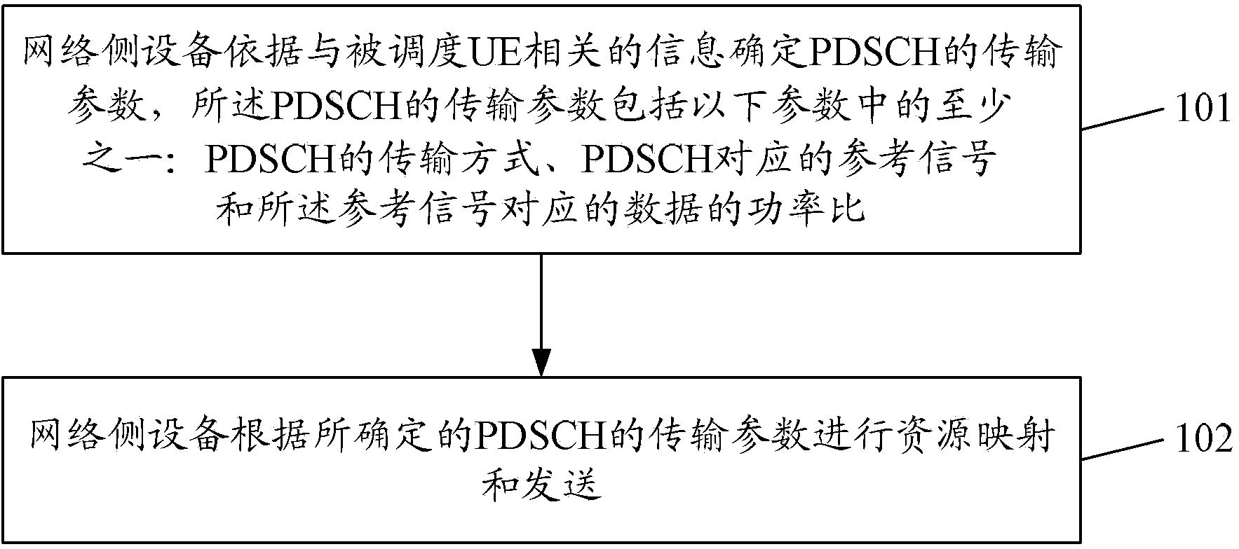
[0243] The network-side device uses the newly added carrier type to transmit data, and the transmitted data corresponds to a single transmission block. The network-side device combines the UE's transmission mode, UE version and support capability information, and the serving cell where the PDSCH is located based on the channel status indication information reported by the UE. The type information and the subframe type information of the PDSCH determine the transmission parameters of the PDSCH; assuming that the version of the UE is a UE that supports NCT, the serving cell type of the UE is NCT, and the transmission mode configured by the UE is TM10 or TM9, the PDSCH If there is no CRS transmission or only RCRS transmission in the subframe, the transmission mode of a single DMRS antenna port is selected. According to the resource mapping corresponding to a single DMRS antenna port, the Localized / Distributed VRB indicator bit in the physical layer control signaling DCI Format 1A i...

Embodiment 2

[0245] The network-side device uses the newly added carrier type to transmit data, and the transmitted data corresponds to a single transmission block. The network-side device combines the UE's transmission mode, UE version and support capability information, and the serving cell where the PDSCH is located based on the channel status indication information reported by the UE. The type information and the subframe type information of the PDSCH determine the transmission parameters of the PDSCH. Assume that the version of the UE is a UE that supports NCT, the serving cell type of the UE is NCT, and the transmission mode configured by the UE is TM10 or TM9. If there is no CRS transmission or only RCRS transmission in the subframe, the transmission mode of a single DMRS antenna port is selected, and according to the resource mapping corresponding to a single DMRS antenna port, the Localized / Distributed VRB indicator bit in the physical layer control signaling DCI Format 1A is used, ...

Embodiment 3

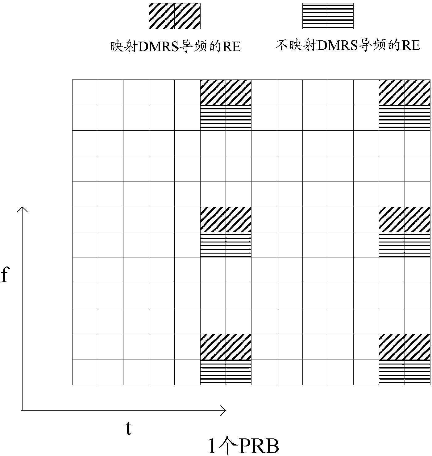
[0249] The network-side equipment uses the new carrier type to transmit data, and the transmitted data corresponds to a single transmission block. The network side combines the UE's transmission mode, UE version and support capability information, and the serving cell type where the PDSCH is located based on the channel status indication information reported by the UE. information, the subframe type information of PDSCH to determine the transmission parameters of PDSCH, assuming that the version of the UE is a UE that supports NCT, the serving cell type of the UE is NCT, and the transmission mode configured by the UE is TM10 or TM9, the subframe where the PDSCH is located If the frame has no CRS transmission or only RCRS transmission, select the transmission mode of a single DMRS antenna port, and map according to the resources corresponding to multiple DMRS ports. For example, assume that the DMRS ports are (7, 8, 9, 10), but only use the One of the DMRS port positions is used...


PUM


Abstract

Disclosed are a method and a system for transmitting a physical downlink shared channel (PDSCH), and a network side device. The method comprises the following steps: (101) a network side device determining a transmission parameter of a PDSCH according to information related to a scheduled user equipment (UE), the transmission parameter of the PDSCH comprises at least one of the following parameters: a transmission mode of the PDSCH, a reference signal corresponding to the PDSCH and a power ratio of data corresponding to the reference signal, and the information related to the scheduled UE comprising at least one of the following items: channel state information reported by the UE, a transmission mode of the UE, a version of the UE and support capability information, type information of a serving cell where the PDSCH is located, type information of a subframe where the PDSCH is located; and (102) the network side device mapping and sending a resource according to the determined transmission parameter of the PDSCH.

Description

technical field [0001] The present invention relates to the field of wireless communication, in particular to a physical downlink shared channel transmission method, system and network side equipment. Background technique [0002] The Long-Term Evolution (LTE, Long-Term Evolution) standard defines a Physical Downlink Control Channel (PDCCH, Physical Downlink Control Channel), which is used to carry downlink control information (DCI, Downlink Control Information), including: uplink and downlink scheduling information, and uplink power control information. The DCI format (DCI Format) in LTE version 11 (Release11, referred to as R11) is divided into the following types: DCI Format 0, DCI Format 1, DCI Format 1A, DCI Format 1B, DCI Format 1C, DCI Format 1D, DCI Format, DCI Format 2A, DCI Format 2B, DCI Format 2C, DCI Format 2C, DCI Format 3, DCI Format 3A, DCI Format 4, etc. With the development of Coordinated Multiple Points (CoMP, Coordinated Multiple Points) technology, the...

Claims


Application Information

Patent Timeline
IPC IPC(8): H04W72/14
CPCH04W72/1273H04L5/0051H04L5/0048H04W72/23H04W72/0453
Inventor 韩晓钢戴博彭佛才
Owner ZTE CORP
Why Eureka
Try Eureka