A profile automatic punching machine

A punching machine, automatic technology, applied in the direction of automatic control device, driving device, boring/drilling, etc., can solve the problem of inability to guarantee the relative position accuracy of holes, low production efficiency, and failure to meet the basic requirements of qualified products, etc. problems, to achieve high production efficiency, ensure positional accuracy, flexible and convenient operation

Active Publication Date: 2016-10-19
中略装备无锡有限公司
View PDF7 Cites 1 Cited by
  • Summary
  • Abstract
  • Description
  • Claims
  • Application Information

AI Technical Summary

Problems solved by technology

Such a processing method has low production efficiency, and cannot guarantee the relative position accuracy between holes, and often fails to meet the basic requirements of qualified products.

Method used


Image

  • A profile automatic punching machine
  • A profile automatic punching machine
  • A profile automatic punching machine

Examples


Embodiment

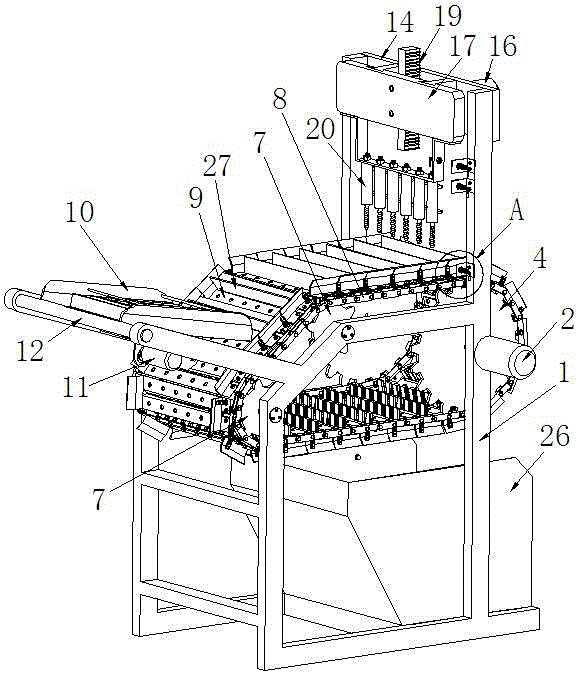
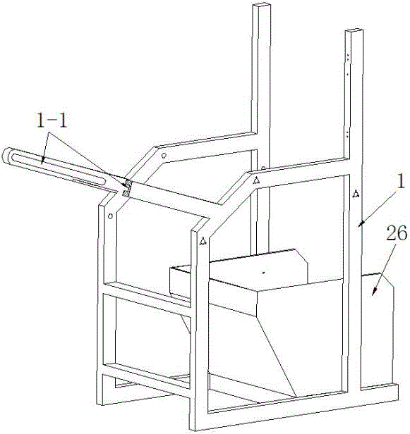
[0027] Example: see attached figure 1 ~ attached Figure 10 , an automatic punching machine for profiles, comprising a frame 1, a transmission mechanism, a feeding mechanism, and a punching mechanism located above the transmission mechanism.

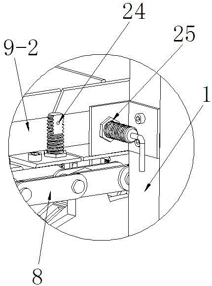
[0028] The transmission mechanism includes a transmission motor 2 fixed on the frame 1, a main shaft 3, two large sprockets 4 coaxial with the main shaft 3 and respectively fixed at both ends of the main shaft 3, an auxiliary shaft 1 parallel to the main shaft 3 and an auxiliary shaft 2 6, four small sprockets 7, two chains 8, 25 continuous long track shoes 9 side by side, one end of the main shaft 3 is fixedly connected to the output shaft of the transmission motor 2, and the other end of the main shaft 3 is movably connected to the machine through a bearing. Frame 1, the two ends of auxiliary shaft 1 5 and auxiliary shaft 2 6 are respectively movably connected to frame 1 through bearings, auxiliary shaft 1 5 is located at the upper po...


PUM


Abstract

The invention relates to an automatic profile perforating machine which comprises a stander, a transmission mechanism, a material conveying mechanism and a perforating mechanism positioned above the transmission mechanism, wherein the transmission mechanism comprises a transmission motor, a main shaft, two large chain wheels respectively fixed at two ends of the main shaft, two auxiliary shafts parallel to the main shaft, four small chain wheels, two chains and at least two side-by-side continuous long-strip crawler plates; the perforating mechanism comprises a carrying plate, a vertical guide rail fixed on the carrying plate, a perforating motor, a lifting plate matched with the guide rail, a gear connected with the perforating motor, a rack which is fixed on the lifting plate and is meshed with the gear and a pneumatic drill bit vertically fixed below the lifting plate. The automatic profile perforating machine is used for realizing continuous material conveying of multiple profile workpieces and automatic drilling of a single row of multiple holes; the production efficiency is high; the position precision among the multiple holes is guaranteed, and the operation is flexible and convenient; the automatic profile perforating machine is more suitable for perforation on profile workpieces with turning edges.

Description

technical field [0001] The invention relates to an automatic punching machine for profiles, which belongs to mechanical equipment. Background technique [0002] Some window and door frame profiles require single row drilling of holes before assembly. In the existing technology, a worker generally places a single profile on a simple single-row perforated formwork, and then drills one by one with a pneumatic drill. Such a processing method has low production efficiency, and cannot guarantee the relative position accuracy between holes, and often fails to meet the basic requirements of qualified products. Contents of the invention [0003] In order to solve the above problems, the present invention provides an automatic punching machine for profiles, which has high production efficiency, ensures the position accuracy between holes, and is flexible and convenient to operate. [0004] To achieve the above object, the specific scheme of the present invention is: [0005] An a...

Claims


Application Information

Patent Timeline
Patent Type & Authority Patents(China)
IPC IPC(8): B23B39/16B23B41/00B23B47/00B23Q7/03
CPCB23B39/162B23Q5/06B23Q7/035B23Q15/013
Inventor 李洪达李洪明
Owner 中略装备无锡有限公司
Why Eureka
Try Eureka