Forward and reverse automatic detachable drill pipe for mining

An automatic disassembly, forward and reverse technology, applied in the direction of drill pipe, drill pipe, earthwork drilling, etc., can solve the problems that cannot meet the operation requirements of automatic drilling rigs, require manual cooperation, and cannot realize automatic disassembly of drilling rigs, etc.

Active Publication Date: 2020-10-23
CHINA COAL TECH & ENG GRP CHONGQING RES INST CO LTD
View PDF7 Cites 0 Cited by
  • Summary
  • Abstract
  • Description
  • Claims
  • Application Information

AI Technical Summary

Problems solved by technology

Although the drill pipe with the square joint or spline sleeve structure currently used can realize the function of forward and reverse rotation, it cannot realize the automatic disassembly of the drilling rig, so it cannot meet the operation requirements of the automatic drilling rig
[0004] Therefore, in order to solve the problem that the existing coal mine reversible drill pipe requires manual cooperation and cannot realize the automatic disassembly of the drilling rig, the present invention provides a mine-used forward and reverse automatically disassembled drill pipe. A simple mechanism is added inside the ordinary one-way threaded drill pipe joint, and the locking and unlocking between the drill pipes is realized by using the change of the cutting hydraulic pressure when the drill pipe is drilling, and the forward and reverse rotation of the drill pipe is realized to meet the loosening of cuttings and the release of jamming, reducing labor Auxiliary disassembly and assembly links, at the same time, the structure of the threaded connection can realize the automatic disassembly of the drilling rig

Method used


Image

  • Forward and reverse automatic detachable drill pipe for mining
  • Forward and reverse automatic detachable drill pipe for mining
  • Forward and reverse automatic detachable drill pipe for mining

Examples


Embodiment Construction

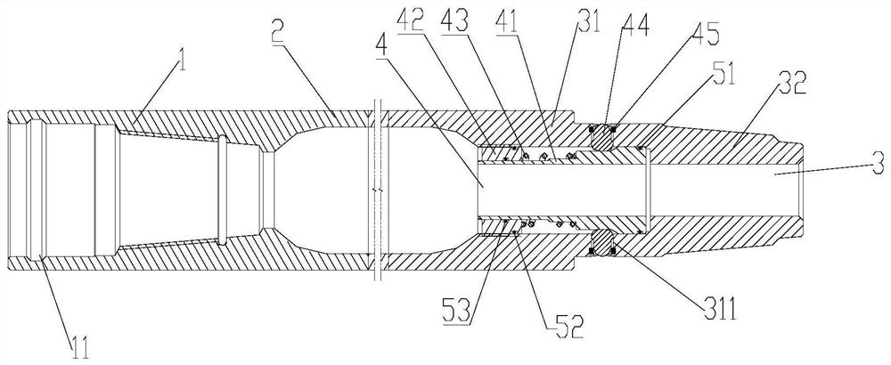
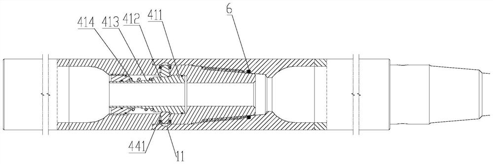
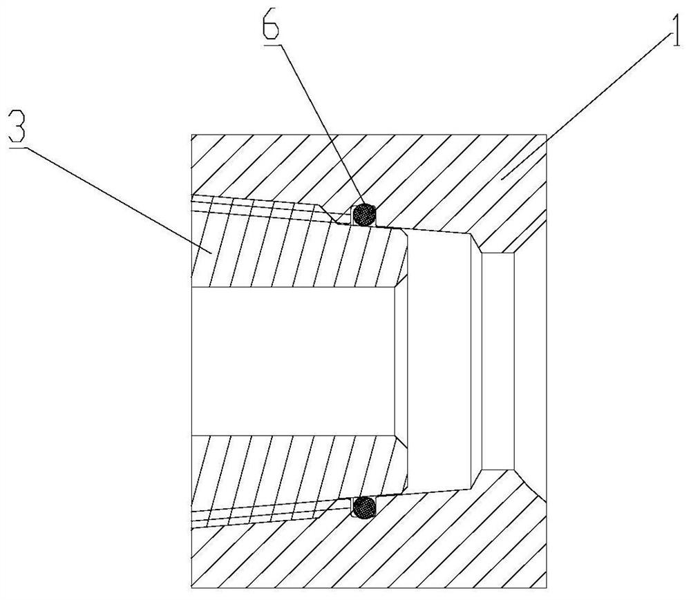
[0021] figure 1 It is a structural schematic diagram of the present invention, figure 2 It is a schematic diagram of the connection structure of the male and female joints of the present invention, image 3 It is an enlarged view of the first sealing ring. As shown in the figure, the mine-used forward and reverse automatic detachable drill pipe in this embodiment includes no less than one drill pipe unit that can be connected in sequence, and the drill pipe unit includes The female joint 1, the pipe body 2 and the male joint 3 are connected in sequence. The two adjacent connected drill pipe units are detachably connected through the cooperation of the male joint 3 and the female joint 1. The male joint 3 includes a hollow hole forming a stepped hole. The control section 31 and the introduction section 32, and the inner diameter of the control section 31 is larger than the inner diameter of the introduction section 32, and a jacking mechanism 4 is arranged in the hole of the ...


PUM


Abstract

The invention discloses a mining forward and reverse rotation automatic dismounting and mounting type drill pipe. The drill pipe comprises more than one drill pipe units which can be sequentially connected. Each drill pipe unit comprises a female joint, a tube body and a male joint which are connected in sequence. The two adjacent drill pipe units are detachably connected through the cooperation of the male joints and the female joints. Each male joint comprises a control section and a lead-in section which are hollow to form a stepped hole, wherein the inner diameter of the control section islarger than the inner diameter of the lead-in section; and a jacking and clamping mechanism is arranged in a hole of the control section and is used for maintaining the connection between or disconnecting the male joints and the female joints in a controlled mode. Simple mechanisms are additionally arranged in an existing common one-way threaded drill pipe joint, drill pipes are locked and unlocked through the change of cuttings hydraulic force during drilling of the drill pipe, forward and reverse rotation of the drill pipe meets the requirements for rock debris cutting and jam release, thelink of using manpower to assist in disassembly and assembly is omitted, and at the time, the threaded connection structure can realize automatic dismounting of a drilling machine.

Description

technical field [0001] The invention relates to the technical field of drilling rig accessories, in particular to a forward and reverse automatic dismountable drilling rod for mining. Background technique [0002] At present, most of the drill pipes used in underground coal mine drilling are conical threaded connections, which can only be twisted in one direction. However, in the actual drilling process, due to the influence of complex strata, hole collapse is very easy to occur, which in turn causes drill sticking and Drill accident. Because the current threaded drill pipe cannot be reversed, its jamming ability is weak. In response to this problem, in recent years, several drill pipe structures that can satisfy forward and reverse operations have been developed successively to improve the jamming ability of the drill pipe. The main structure types are: one is a column and Holes are plugged and docked to transmit forward and reverse torque, and key pins or screws are used...

Claims


Application Information

Patent Timeline
Patent Type & Authority Patents(China)
IPC IPC(8): E21B17/00E21B17/043
CPCE21B17/00E21B17/043
Inventor 潘小叶李彦明张俞王清峰徐树斌郭昆明赵志强李称心梅安平
Owner CHINA COAL TECH & ENG GRP CHONGQING RES INST CO LTD
Why Eureka
Try Eureka