Plastic mold with automatically separated material overflow structure

A technology of overflow structure and plastic mold, applied in the field of plastic mold, can solve the problems of not being able to withstand working load, insufficient strength, product breakage, etc.

Active Publication Date: 2015-02-18
NINGBO TIANLONG ELECTRONICS
View PDF4 Cites 2 Cited by
  • Summary
  • Abstract
  • Description
  • Claims
  • Application Information

AI Technical Summary

Problems solved by technology

[0008] Figure 8 It is a three-dimensional axonometric view of the product and flow channel produced by the traditional one-mold four-cavity mold. image 3 The fusion at the end F of the filling shown will cause product 2 to form a weld line F' at the intersection of the two plastics

Method used


Image

  • Plastic mold with automatically separated material overflow structure
  • Plastic mold with automatically separated material overflow structure
  • Plastic mold with automatically separated material overflow structure

Examples


Embodiment Construction

[0046] With reference to accompanying drawing, further illustrate the present invention:

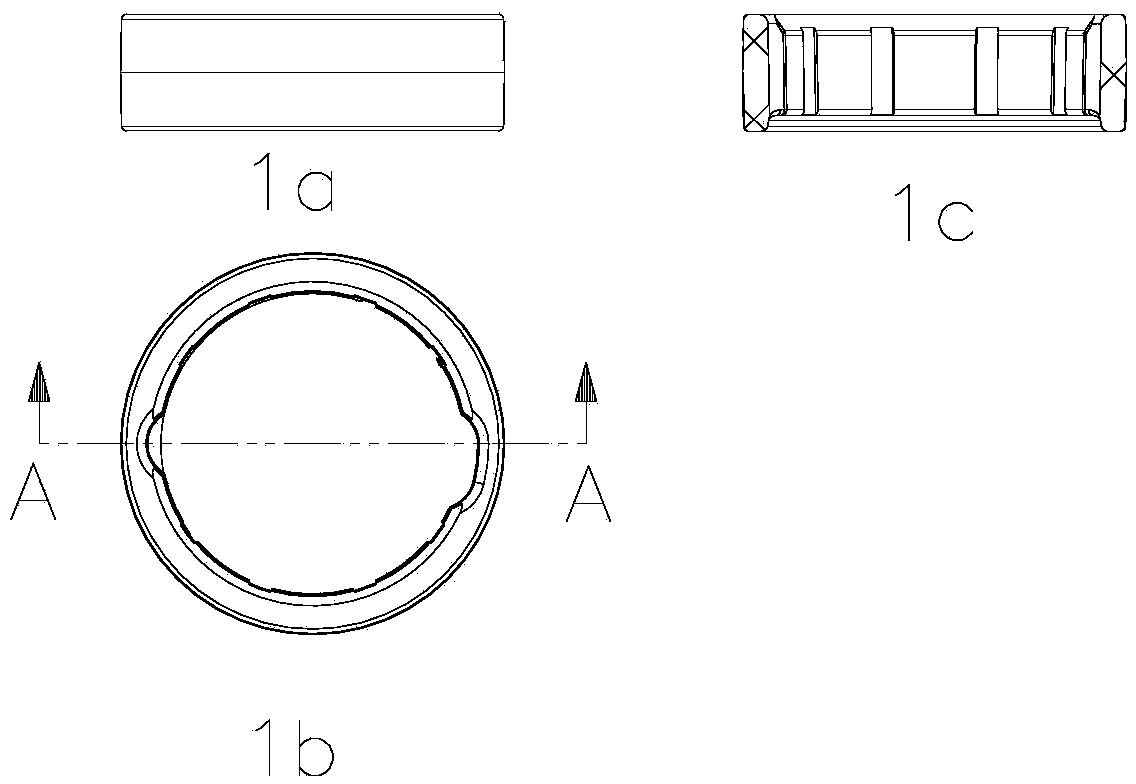
[0047] A plastic mold with an automatically separable overflow structure, comprising a combined movable template 8 and a fixed template 10, the movable template 8 reciprocates longitudinally to complete mold opening or mold closing, and the movable template 8 is provided with There is a movable mold core 9, a fixed mold core 11 is arranged on the fixed template 10, and a molding cavity of a plastic product is provided on the parting surface between the movable mold core 9 and the fixed mold core 11. The cavity is connected to the pouring mechanism;

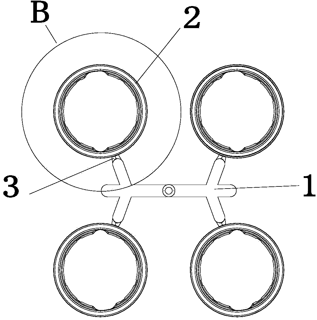
[0048] The movable template 8 is provided with a longitudinally moving thimble backing plate 4 and a thimble fixing plate 5, and the thimble backing plate 4 is connected to the thimble fixing plate 5; The runner thimble 6 of the runner 1, the thimble 14 and the pulling rod 7 for ejecting the product 2;

[0049] The mold cavity communicates...


PUM


Abstract

The invention discloses a plastic mold with an automatically separated material overflow structure. A cavity is communicated with a runner through a single-side pouring gate; plastic in the runner enters the cavity after being divided into two strands from the single-side pouring gate and then is gathered at the tail filling end; the plastic mold further comprises the material overflow structure arranged at the tail filling end and a material overflow mandril of the material overflow structure; the material overflow structure comprises a convex boss and a concave boss; the convex boss comprises a material overflow cavity communicated with the cavity; a reverse tunnel gate is formed in one end of the material overflow cavity and is connected with the tail filling end of the cavity; the other end of the material overflow cavity is communicated with a balance pipe; the length of the balance pipe is equal to that of the reverse tunnel gate; a mandril hole is formed between the reverse tunnel gate and the balance pipe; the length of the mandril hole is equal to that of the balance pipe; the material overflow mandril is fixed on a thimble fixing plate. According to the plastic mold, the problem that the product intensity is low because of a dissolving trace is effectively solved, and the problems existing in automatic separation of the material overflow structure are solved.

Description

technical field [0001] The invention relates to a plastic mold with an automatically detachable flash structure. technical background [0002] 1. Ring-shaped products: [0003] figure 1 It is a schematic diagram of the structure of the product that is required to be produced. Its material is PA66 (nylon 66), and its diameter is 41.4mm. It is required that after injection molding, it cannot break under the condition that it can withstand a certain load during use. [0004] figure 2 Schematic diagram of the traditional one-mold four-cavity mold structure for the production of products, including runner 1, product 2, and single-side gate 3. [0005] image 3 for figure 2 It can be seen from this figure that the plastic enters the cavity of the product along the single-side gate 3 at C and will be divided into two streams, one flows in the direction indicated by the arrow D, and the other flows along the direction indicated by the E arrow. Flow in the direction indicated...

Claims


Application Information

Patent Timeline
IPC IPC(8): B29C45/32
CPCB29C45/2669B29C45/32
Inventor 张劲松
Owner NINGBO TIANLONG ELECTRONICS
Why Eureka
Try Eureka