
Stroke detection device for crane steel rope

A technology of stroke detection and steel wire rope, which is applied in the field of detection devices, can solve the problems of insufficient precision, troublesome use and adjustment, etc., and achieve the effect of precise control of lifting height and precise control of descending stroke

Inactive Publication Date: 2015-02-18
韶关市博仕乐液压机械制造有限公司
View PDF7 Cites 4 Cited by
  • Summary
  • Abstract
  • Description
  • Claims
  • Application Information

AI Technical Summary

Problems solved by technology

However, for telescopic jib cranes, a wiring mechanism is required to transmit signals, which is troublesome to use and adjust
[0004] For the over-discharge limit of the crane, the existing technology generally uses the drum rotation to obtain signals to determine the position of the last three turns. Since the wire rope has different winding levels on the drum, the last three turns are determined by the drum rotation position. Insufficient precision

Method used


Image

  • Stroke detection device for crane steel rope

Examples


Embodiment Construction

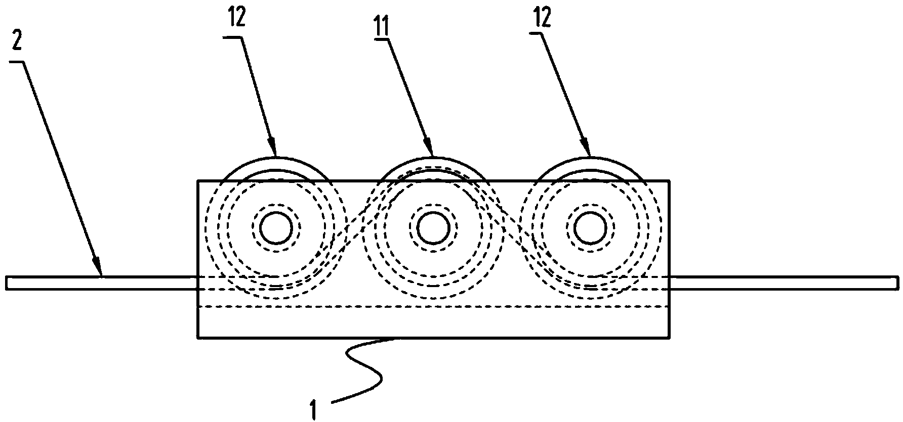
[0014] see figure 1 , which is a structural schematic diagram of the crane wire rope stroke detection device of the present invention. It includes a pulley block 1 composed of three pulleys side by side, and a displacement sensor is arranged on the middle pulley. Specifically, in this embodiment,

[0015] For better understanding and implementation, the present invention will be described in detail below in conjunction with the accompanying drawings. Described pulley block comprises 3 pulleys, wherein is positioned at the main pulley 11 of middle pulley, and the pulley that is positioned at main pulley two ends is auxiliary pulley 12. The crane wire rope 2 is hung on the top of the main pulley 11 , and the two ends of the wire rope go out along the bottom of the auxiliary pulley 12 .

[0016] During the working process, the up and down movement of the crane hook is realized by the rotation of the drum. When performing over-rolling limit, the displacement travel during the ...


PUM


Abstract

The invention relates to a stroke detection device for a crane steel rope. The stroke detection device comprises a pulley block composed of at least three pulleys, wherein a displacement sensor is arranged on one pulley. Compared with the prior art, the stroke detection device has the advantages as follows: as one pulley block is used, the close fit of the steel rope and the pulleys can be ensured, and the stroke of the hoisting steel rope can be precisely detected, the stroke detection device can carry out overwinding and overunwinding limiting of a crane and can accurately control the position of a grab hook. The invention further relates to a limiting and controlling method for a crane hoisting mechanism using the detection device.

Description

technical field [0001] The invention relates to a detection device, in particular to a crane wire rope stroke detection device. Background technique [0002] When the crane uses steel wire rope to lift heavy objects, in order to ensure the safety of the crane, it is necessary to control the wire rope over-rolling limit and over-release limit. Among them, the over-rolling limit of the crane is mainly to prevent the hoisting hook from continuing to lift to cause damage to the machine and cause accidents; Make sure that the wire rope is fixed on the drum. [0003] Aiming at the limit of the overwinding of the crane, the prior art generally uses a weight switch set on the hoisting wire rope to limit the position. The general over-rolling limit device is to hang a heavy hammer next to the fixed pulley, set it on the wire rope, and the rope hanging the heavy hammer pulls a switch. When the lifting hook reaches the maximum lifting height, the heavy hammer is lifted and the heavy ...

Claims


Application Information

Patent Timeline
IPC IPC(8): B66C13/16
CPCB66C13/16B66C1/56
Inventor 钟于民廖惠鹏
Owner 韶关市博仕乐液压机械制造有限公司
Learn More