Commutator rotor processing device and application method thereof

A technology of processing device and commutator, applied in positioning device, grinding drive device, metal processing equipment, etc., can solve the problems affecting rotor quality, rotor rotation operation deviation, insufficient rotor machining accuracy, etc., to improve the processing quality , the effect of lifting stability

Pending Publication Date: 2021-12-14
温州鼎龙电子科技有限公司
View PDF0 Cites 1 Cited by
  • Summary
  • Abstract
  • Description
  • Claims
  • Application Information

AI Technical Summary

Problems solved by technology

[0003] The existing commutator rotor cannot accurately control the height of the rotor during processing, which leads to insufficient machining accuracy of the rotor and affects the quality of the rotor. At the same time, the existing commutator rotor processing device cannot achieve a stable rotor fixed so that there is an offset when the rotor is rotated

Method used


Image

  • Commutator rotor processing device and application method thereof
  • Commutator rotor processing device and application method thereof
  • Commutator rotor processing device and application method thereof

Examples


Embodiment 1

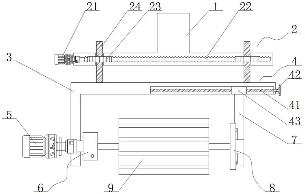
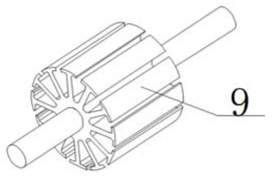
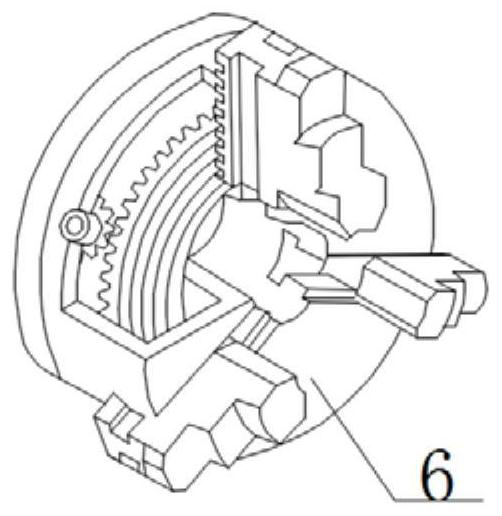
[0028] see figure 1 According to the commutator rotor processing device of the embodiment of the present invention, it includes a fixed block 1, the inside of the fixed block 1 is provided with a lifting mechanism 2, the bottom end of the lifting mechanism 2 is provided with a fixing frame 3, and the inside of the fixing frame 3 is provided with a horizontal The moving mechanism 4, the lower left end of the fixed frame 3 is fixedly connected with the main reducer 5, the end of the main shaft of the main reducer 5 is fixedly connected with the three-jaw chuck 6, the bottom end of the horizontal moving mechanism 4 is provided with a fixed plate 7, the fixed plate 7 The left end of is provided with clamping mechanism 8, and the inboard of three-jaw chuck 6 and clamping mechanism 8 is provided with commutator rotor 9.

[0029] The lifting mechanism 2 includes a servo motor 21, the end of the main shaft of the servo motor 21 is fixedly connected with a worm 22, the front end of the...

Embodiment 2

[0032] see Figure 1-4 According to the commutator rotor processing device of the embodiment of the present invention, it includes a fixed block 1, the inside of the fixed block 1 is provided with a lifting mechanism 2, the bottom end of the lifting mechanism 2 is provided with a fixing frame 3, and the inside of the fixing frame 3 is provided with a horizontal The moving mechanism 4, the lower left end of the fixed frame 3 is fixedly connected with the main reducer 5, the end of the main shaft of the main reducer 5 is fixedly connected with the three-jaw chuck 6, the bottom end of the horizontal moving mechanism 4 is provided with a fixed plate 7, the fixed plate 7 The left end of is provided with clamping mechanism 8, and the inboard of three-jaw chuck 6 and clamping mechanism 8 is provided with commutator rotor 9.

[0033] The horizontal movement mechanism 4 comprises a second screw mandrel 41, the second screw mandrel 41 is rotationally connected with the fixed frame 3, th...


PUM


Abstract

The invention relates to a commutator rotor processing device. The device comprises a fixing block and is characterized in that a lifting mechanism is arranged at the inner side of the fixing block, a fixing frame is arranged at the bottom end of the lifting mechanism, a horizontal moving mechanism is arranged at the inner side of the fixing frame, and a main speed reducer is fixedly connected to the left end of the lower side of the fixing frame; and the tail end of a main shaft of the main speed reducer is fixedly connected with a three-jaw chuck, a fixing plate is arranged at the bottom end of the horizontal moving mechanism, a clamping mechanism is arranged at the left end of the fixing plate, a commutator rotor is arranged at the inner side of the three-jaw chuck and the inner side of the clamping mechanism, and the device is easy and convenient to operate and prevents the commutator rotor from deviating in the machining process.

Description

technical field [0001] The invention relates to the field of auto parts processing devices, in particular to a commutator rotor processing device and a use method thereof. Background technique [0002] The commutator rotor is an important part of the DC motor and the armature of the AC commutator motor. It is used as a commutation of the current on the DC motor and the AC series motor. In order to make the motor continue to rotate, it is commonly known as the commutator. The motor is used as Indispensable and important basic equipment in industry, transportation, national defense and daily life, its downstream industries include almost all basic industries of the national economy. As one of the core components of the motor, the commutator is also growing with the development of the motor industry. When the commutator rotor is processed, it needs to be fixed by a device to perform various operations. [0003] The existing commutator rotor cannot accurately control the height...

Claims


Application Information

Patent Timeline
Patent Type & Authority Applications(China)
IPC IPC(8): B23Q3/06B24B41/06B24B47/12B24B47/22
CPCB23Q3/062B24B41/06B24B47/12B24B47/22
Inventor 许道雪王杰
Owner 温州鼎龙电子科技有限公司
Why Eureka
Try Eureka