Pushing device

A pusher and pusher technology, applied in the field of pushers, can solve the problems of insufficient pusher protection, easily damaged pushers, and high maintenance costs, and achieve the effects of enhanced work continuity, reliable protection, and improved service life.

Inactive Publication Date: 2015-02-18
无锡晶瑜智能机械有限公司
View PDF1 Cites 8 Cited by
  • Summary
  • Abstract
  • Description
  • Claims
  • Application Information

AI Technical Summary

Problems solved by technology

[0003] The pusher in the traditional walking furnace does not protect the push rod enough. During use, the push rod is often easily damaged, resulting in high maintenance costs and affecting normal production.

Method used


Image

  • Pushing device

Examples


Embodiment Construction

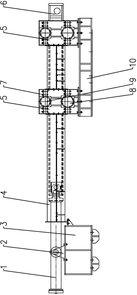
[0013] Below the present invention will be further described in conjunction with the embodiment in the accompanying drawing:

[0014] Such as figure 1 As shown, the present invention mainly includes a hydraulic cylinder 1, a roller shaft assembly 5 and a push rod 6. The front end of the piston rod of the hydraulic cylinder 1 is connected to the push rod 6, and the front end of the push rod 6 passes through the two roller shaft assemblies 5.

[0015] The roller shaft assembly 5 includes a roller shaft seat 7 , in which a pressing roller 9 and an idler roller 8 are arranged from top to bottom, and the push rod 6 passes between the pressing roller 9 and the idler roller 8 .

[0016] The hydraulic cylinder 1 is fixed on the front base 3 through a support 2 .

[0017] The roller assembly 5 is fixed on the rear base 10 .

[0018] The front end of the hydraulic cylinder 1 is provided with a protective cover 4, and the protective cover 4 covers the push rod 6 to protect the push rod...


PUM


Abstract

The invention relates to a pushing device, in particular to pushing equipment which can reliably protect a push rod, belonging to the technical field of pushing devices. The pushing device comprises a hydraulic cylinder, roller shaft components and a push rod, wherein the push rod is connected to the front end of the piston rod of the hydraulic cylinder; the front end of the push rod penetrates through two roller shaft components; the roller shaft components comprise roller shaft bases; pressing rollers and support rollers are arranged inside the roller shaft bases from top to bottom; the push rod penetrates through the pressing rollers and the support rollers. The pushing device is simple, compact and reasonable in structure, the push rod is reliably protected, the service life of the push rod is prolonged, and the working continuity is improved.

Description

technical field [0001] The invention relates to a pusher, in particular to a pusher capable of reliably protecting a push rod, and belongs to the technical field of pushers. Background technique [0002] Walking furnace is a kind of "continuous heating heat treatment equipment" widely used in industrial heat treatment industry. The furnace is structurally divided into furnace body, heating mechanism (electric heating or flame heating), moving mechanism (moving beam moving part, furnace door lifting part, feeding / discharging part machinery, etc.), control part and so on. [0003] The pusher in the traditional walking furnace does not protect the push rod enough. During use, the push rod is often easily damaged, resulting in high maintenance costs and affecting normal production. Contents of the invention [0004] The object of the present invention is to overcome the above disadvantages, thereby providing a pusher that can reliably protect the push rod, increase the servic...

Claims


Application Information

Patent Timeline
Patent Type & Authority Applications(China)
IPC IPC(8): C21D9/00F27D3/04
CPCC21D9/0018
Inventor 赵军
Owner 无锡晶瑜智能机械有限公司
Why Eureka
Try Eureka