
Constraint measuring tool and using method thereof

A measuring tool and a technology to be tested, applied in the direction of measuring devices and instruments, etc., can solve the problems of unreasonable structure of the restraint measuring tool and large numerical deviation, and achieve the effect of meeting the requirements of design drawings and actual use

Inactive Publication Date: 2015-02-18
SHENYANG LIMING AERO-ENGINE GROUP CORPORATION
View PDF6 Cites 6 Cited by
  • Summary
  • Abstract
  • Description
  • Claims
  • Application Information

AI Technical Summary

Problems solved by technology

However, the structure of the existing restraint measuring tools is not reasonable, which makes the numerical deviation measured by this detection method also very large

Method used


Image

  • Constraint measuring tool and using method thereof
  • Constraint measuring tool and using method thereof

Examples


Embodiment Construction

[0018] The present invention will be further described in detail below in conjunction with the accompanying drawings and specific embodiments.

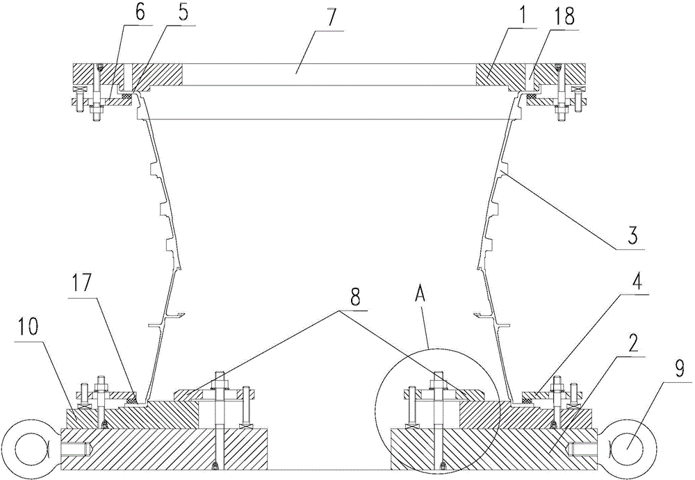
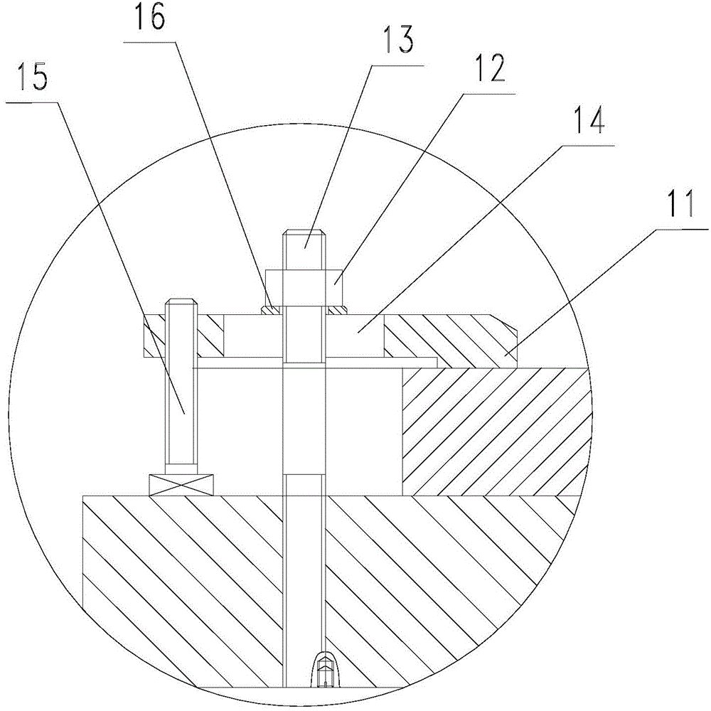
[0019] Such as figure 1 As shown, a constraint measuring tool includes a base 2, a gland 1 is arranged above the base 2, and a positioning ring 10 is arranged on the upper surface of the base 2, and the positioning ring 10 is fixed on the On the base 2; the upper surface of the locating ring 10 corresponds to the benchmark 17 of the part to be detected, and the lower surface of the gland 1 corresponds to the notch 5 of the part to be detected; the locating ring 10 and the part 3 to be detected are compressed by the first The device 4 is fixedly connected, and the gland 1 and the part 3 to be tested are fixedly connected through the second pressing device 6 . The gland 1 is provided with an observation hole 7 and a detection through hole 18. The observation hole 7 is sufficiently open to facilitate probe measurement. The detection thr...


PUM


Abstract

The invention discloses a constraint measuring tool and a using method thereof and belongs to the technical field of aeroengine casing part machining detection. The measuring tool comprises a base, a pressing cover is arranged above the base, and the upper surface of the base is provided with a positioning ring which is fixed to the base through a third pressing device; the upper surface of the positioning ring corresponds to the reference of a part to be detected, and the lower surface of the pressing cover corresponds to the spigot of the part to be detected; the positioning ring is fixedly connected to the part to be detected through a first pressing device, the pressing cover is fixedly connected to the part to be detected through a second pressing device. The using method includes placing the positioning ring on the upper surface of the base, and pressing and fixing the positioning ring through the third pressing device; placing the part to be detected onto the top of the positioning ring, matching the upper surface of the positioning ring with the reference of the part to be detected, and pressing and fixing the positioning ring and the part to be detected through the first pressing device; placing the pressing cover onto the top of the part to be detected, matching the spigot of the part to be detected with the lower surface of the pressing cover, and pressing and fixing the part to be detected and the pressing cover through the second pressing device.

Description

technical field [0001] The invention belongs to the technical field of mechanical processing and detection of aero-engine casing parts, and in particular relates to a constraint measuring tool and a method for using the same, which are mainly used in the technical condition and dimension detection of aero-engine casing parts. Background technique [0002] Aircraft engine casing parts are generally thin-walled parts, and the results of the technical conditions of the parts are inconsistent under different measurement conditions; in order to truly reflect the actual state of the parts, the actual detection method should be able to match the actual assembly requirements of the parts, and the detection results can be true. Representing the delivery status of the part is a reasonable detection method. There are usually three detection methods for casing parts: machine tool compression state detection, constraint state detection and completely free state detection. The detection ...

Claims


Application Information

Patent Timeline
Patent Type & Authority Applications(China)
IPC IPC(8): G01B21/00
CPCG01B21/00
Inventor 王丽花唐秀梅张建国于洋
Owner SHENYANG LIMING AERO-ENGINE GROUP CORPORATION
Learn More