
Contactor

A technology of contactors and contact bridges, applied in the direction of relays, electromagnetic relays, detailed information of electromagnetic relays, etc., can solve the problems of unfavorable modular production, bulky contactors, and low assembly efficiency, and achieve ingenious connection structure, small size, The effect of improving assembly efficiency

Active Publication Date: 2015-02-18
ZHEJIANG CHINT ELECTRIC CO LTD
View PDF5 Cites 8 Cited by
  • Summary
  • Abstract
  • Description
  • Claims
  • Application Information

AI Technical Summary

Problems solved by technology

[0002] The arc extinguishing chamber of the existing contactor is also the entire base of the contactor. The arc extinguishing grid is directly riveted in the small cavity of the base. The base is pressed from non-recyclable thermosetting plastic materials, such as thermosetting phenolic or DMC, the contactor of this arc extinguishing device structure is relatively bulky and not environmentally friendly
In addition, the existing contactor has a complex structure, which is not conducive to modular production and has the problems of low assembly efficiency

Method used


Image

  • Contactor
  • Contactor
  • Contactor

Examples


Embodiment Construction

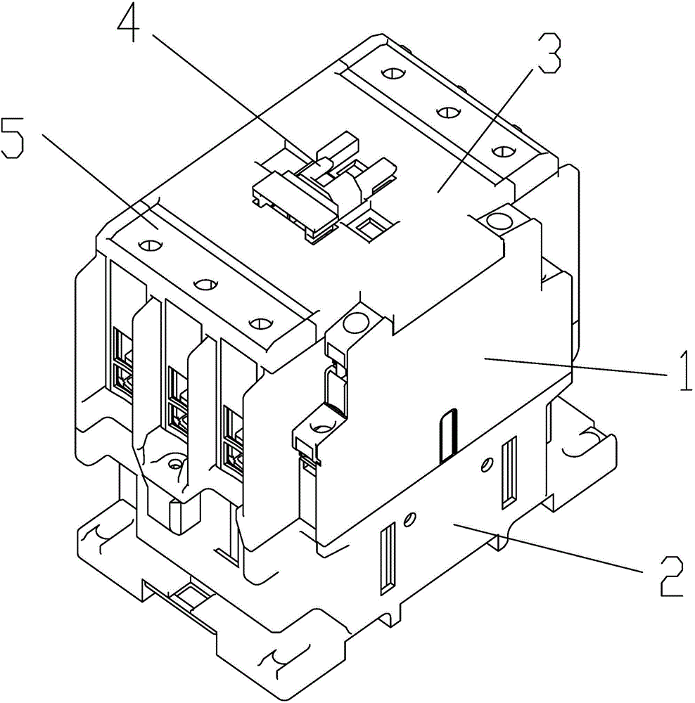
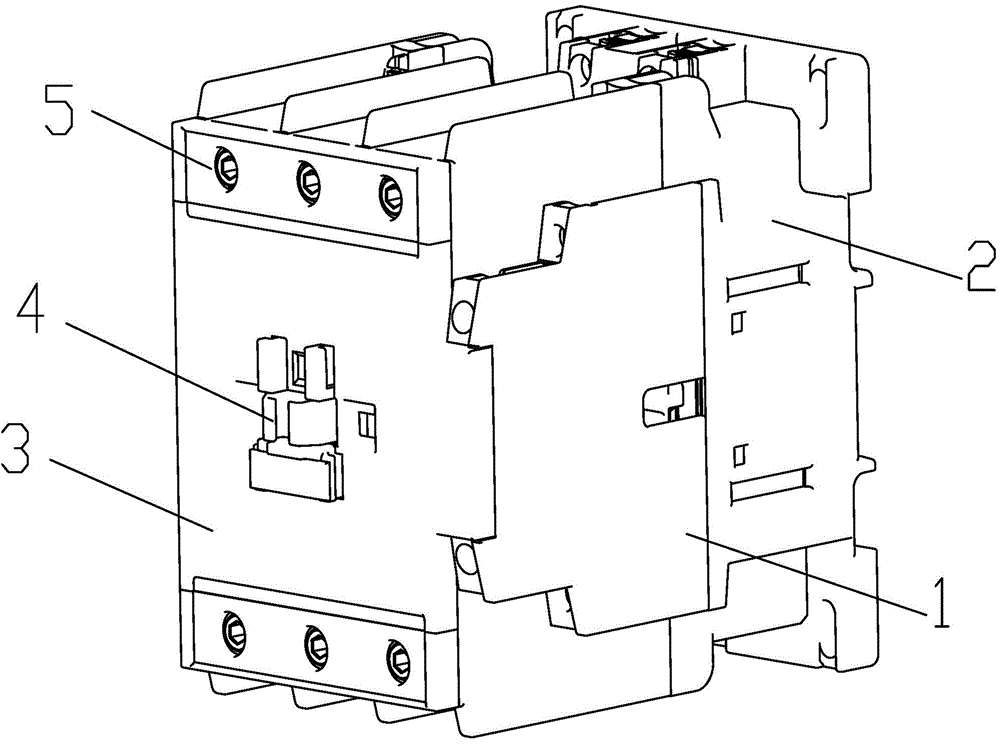
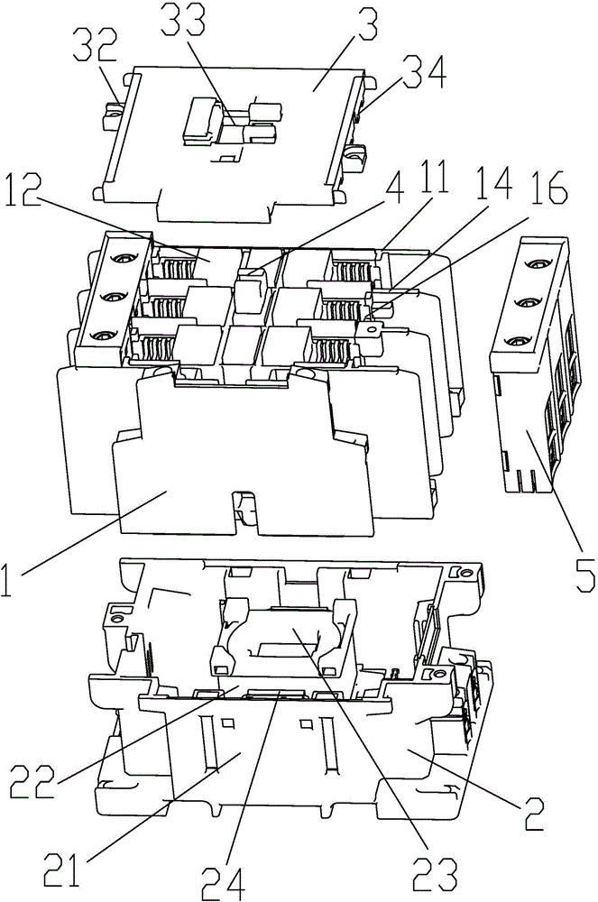
[0024] The following is attached Figures 1 to 4 The given examples further illustrate the specific implementation of the contactor of the present invention. The contactor of the present invention is not limited to the description of the following embodiments.

[0025] Such as Figure 1-4 As shown, the contactor of the present invention includes a base assembly 2 , a base assembly 1 and a top cover 3 , the base assembly 1 is fixedly connected to the base assembly 2 , and the top cover 3 is fixedly connected to the base assembly 1 . The base assembly 2 includes a base 21 and an electromagnet 22 disposed in the base 21 , the electromagnet 22 includes a coil 23 and a fixed iron core 24 . The base assembly 1 includes a base 11, a contact assembly 13 arranged in the base 11, an arc extinguishing unit 12 and a contact support 4; pole separators 14 are provided on both sides of the base 11 to accommodate each pole The unit cavity 16 of the conductive system, each unit cavity 16 is...


PUM


Abstract

A contactor comprises a base component, a foundation component and a top cover. The base component comprises a base and an electromagnet disposed in the base. The foundation component comprises a foundation, and contact components, arc extinguishing units and a contact support which are disposed in the foundation. Inter-electrode partitions are disposed on two sides in the foundation to form unit cavities for containing conductive systems. One independent arc extinguishing unit and one contact component including a static contact are disposed in each unit cavity. Each arc extinguishing unit comprises an arc extinguishing chamber and an arc extinguishing grid piece disposed in the arc extinguishing chamber. The contact support is disposed on the middle portion of the foundation. A contact bridge is disposed on the contact support. Two ends of the contact bridge is provided with movable contacts matched with the static contacts on two sides. One end of the contact support is connected with a movable iron core. The top cover is fixedly connected with one end of the foundation. The other end of the foundation is fixedly connected with the base. The movable iron core corresponds to the electromagnet in the base. The contactor using the independent arc extinguishing units is good in arc extinguishing effect, simple in structure, easy to produce, energy saving and environmental friendly.

Description

technical field [0001] The invention belongs to the field of low-voltage electrical appliances, in particular to a contactor. Background technique [0002] The arc extinguishing chamber of the existing contactor is also the entire base of the contactor. The arc extinguishing grid is directly riveted in the small cavity of the base. The base is pressed from non-recyclable thermosetting plastic materials, such as thermosetting phenolic or DMC, the contactor of this arc extinguishing device structure is relatively bulky and not environmentally friendly. In addition, the existing contactor has a complex structure, which is not conducive to modular production and has the problems of low assembly efficiency. Contents of the invention [0003] The purpose of the present invention is to overcome the defects of the prior art and provide a contactor with good arc extinguishing performance, simple structure and easy production. [0004] To achieve the above object, the present inve...

Claims


Application Information

Patent Timeline
Patent Type & Authority Applications(China)
IPC IPC(8): H01H50/00H01H50/04
CPCH01H50/00H01H50/042
Inventor 李婉婷朱映平肖体锋
Owner ZHEJIANG CHINT ELECTRIC CO LTD
Learn More