Intelligent optical control lamp system

An intelligent and bright technology, applied in the field of light control system, can solve the problems of non-adaptive change, waste of power resources, etc.

Inactive Publication Date: 2015-02-25
JIANGNAN UNIV
View PDF0 Cites 12 Cited by
  • Summary
  • Abstract
  • Description
  • Claims
  • Application Information

AI Technical Summary

Problems solved by technology

[0002] Traditional lighting control means that the main power supply is divided into multiple branches through the distribution box to supply power to the lamps. It uses a single (double) pole switch connected in series in the lighting circuit to turn on and off the power supply line to realize the control of the lamps. Therefore, the lamps controlled by the switch can only be controlled on/off, and the brightness adjustment is also adjusted through the ordinary dimmer switch, which cannot be adapti

Method used


Image

  • Intelligent optical control lamp system
  • Intelligent optical control lamp system
  • Intelligent optical control lamp system

Examples


Embodiment Construction

[0015] The patent of the present invention will now be described in further detail with reference to the accompanying drawings. These drawings are simplified schematic diagrams, which only illustrate the basic structure of the patent of the present invention in a schematic manner, so they only show the structures related to the patent of the present invention.

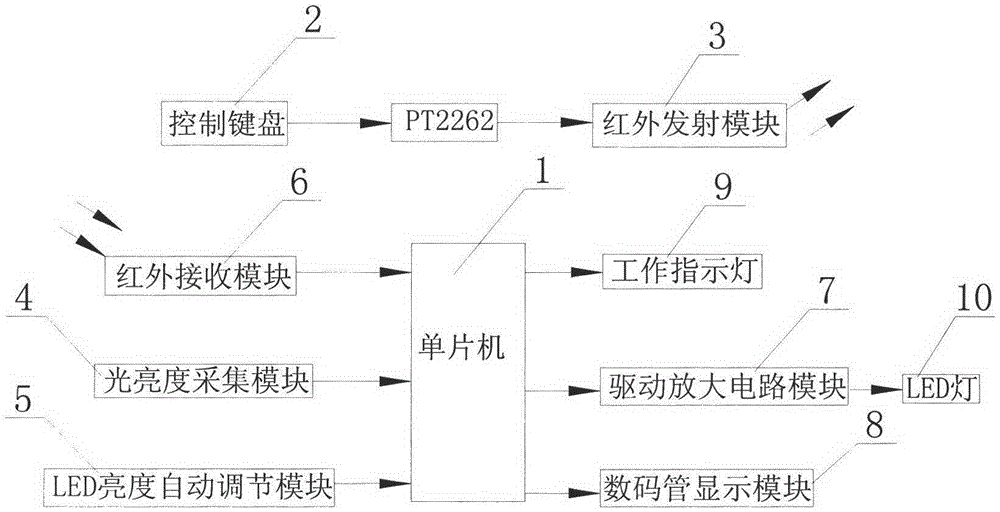
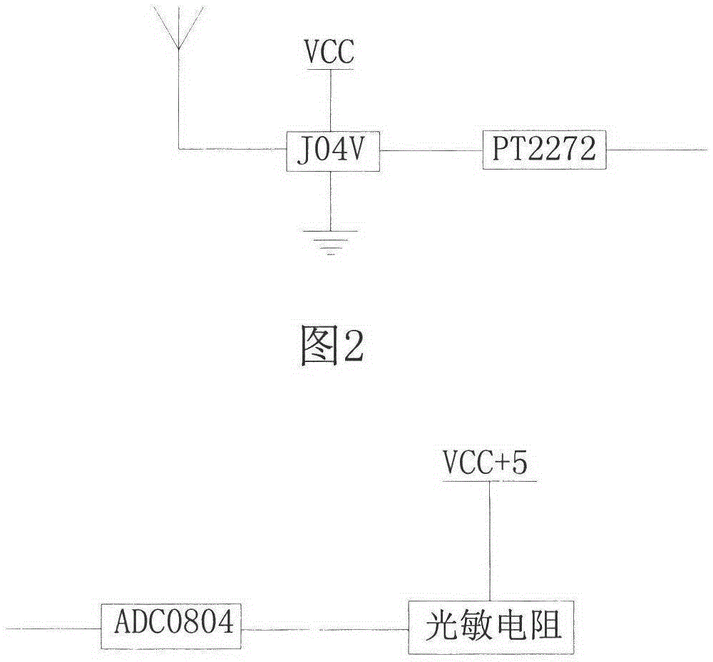
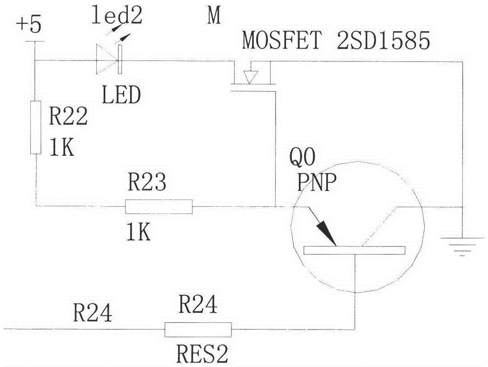
[0016] Such as figure 1 An intelligent light control lamp system shown includes ST89S52 single-chip microcomputer 1, control keyboard 2, infrared emission module 3, light brightness acquisition module 4, LED brightness automatic adjustment module 5, infrared receiving module 6, drive amplifier circuit module 7, digital Tube display module 8 and working indicator 9 and LED light, brightness acquisition module 4 uses ADC0804 chip to detect the voltage across the photoresistor in the photoresistor circuit and convert the voltage signal into a digital signal to send to the single-chip microcomputer 1, and the single-chip 1 col...


PUM


Abstract

The invention relates to an intelligent optical control lamp system which comprises a single-chip microcomputer, a control keyboard and an infrared transmitting module. The input end of the single-chip microcomputer is connected with a brightness acquisition module, an automatic LED brightness adjusting module and an infrared receiving module. Signals are transmitted to the infrared transmitting module by pressing different keys on the control keyboard. The infrared transmitting module will transmit different binary pulse codes to the infrared receiving module. The infrared receiving module converts the received binary pulse codes into binary signals and transmits the binary signals to the single-chip microcomputer. The output end of the single-chip microcomputer is connected with a drive amplifying circuit module, a nixie tube display module and a work indicating lamp. The output end of the drive amplifying circuit module is connected with LED lamps, and the illumination intensity of the LED lamps is displayed through the nixie tube display module. According to the intelligent optical control lamp system, the brightness of the lamp can be adjusted automatically according to the intensity of light rays, the brightness of the lamp can be adjusted manually, and the illumination intensity can be displayed due to the fact that the intelligent optical control lamp system has a nixie tube display function.

Description

Technical field [0001] The patent of the invention relates to the field of light control systems, in particular to an intelligent light control lamp system capable of adjusting lighting in manual and automatic modes. Background technique [0002] Traditional lighting control means that the main power supply is divided into multiple branches through the distribution box to supply power to the lamps. It uses a single (double) pole switch connected in series in the lighting circuit to turn on and off the power supply line to control the lamps. Therefore, the lamp controlled by the switch can only be controlled on / off, and its brightness adjustment is also adjusted by an ordinary dimmer switch, and cannot be adaptively changed according to the light environment to achieve the most comfortable brightness required by the individual. Traditional lighting control not only requires manual control, but also wastes valuable power resources. For a long time, smart lighting has been neglecte...

Claims


Application Information

Patent Timeline
IPC IPC(8): H05B37/02
Inventor 张相胜童亚军孙超丁君颖韩旭张奎
Owner JIANGNAN UNIV
Why Eureka
Try Eureka