Clamp for door processing

A door and fixture technology, applied in the direction of spraying device, etc., can solve the problems of inability to adjust the position of the door, uneven painting of the door, etc., and achieve the effect of avoiding uneven painting and avoiding uneven painting of the door.

Active Publication Date: 2015-03-04
CHONGQING OFAN DOOR IND
View PDF6 Cites 6 Cited by
  • Summary
  • Abstract
  • Description
  • Claims
  • Application Information

AI Technical Summary

Problems solved by technology

[0003] The technical problem to be solved by the present invention is to provide a clamping clamp for the technical defect that the existing door clamp must clamp the surface to be painted of the door when clamping the door and cannot adjust the position of the door, resulting in uneven spraying of the door. A fixture for door processing that does not need to clamp the surface of the door to be painted and can adjust the position of the door

Method used


Image

  • Clamp for door processing
  • Clamp for door processing

Examples


Embodiment Construction

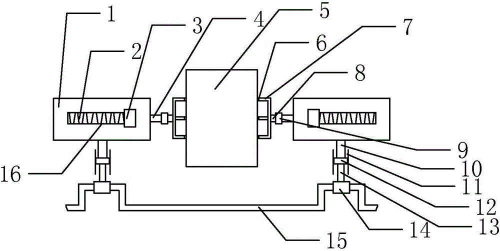
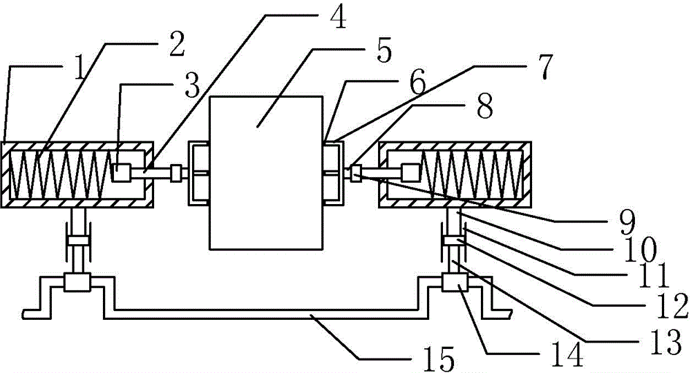
[0014] Sliding box 1, compression spring 2, pressure block 3, support rod 4, door 5, elastic pad 6, chuck 7, connecting rod 8, sleeve 9, support column 10, slideway 11, slider 12, hinge rod 13, drum 14, crankshaft 15, chute 16.

[0015] Such as figure 1 , 2 As shown, the fixture for processing the door 5 of the present invention includes a crankshaft 15 and two oppositely arranged clamping bodies. The crankshaft 15 is wave-shaped, and the crankshaft 15 includes a wave trough and two peaks, and the heights of the two wave peaks are equal; the clamping body includes Slideway 11 and cuboid sliding box 1, slideway 11 is provided with slide block 12, and slide block 12 can move up and down in slideway 11 under the effect of external force, and the lower end of slide block 12 is hinged with hinge rod 13, The lower end of the articulated rod 13 is fixedly connected with a drum 14, and the drums 14 of the two clamp bodies are respectively sleeved on the two crests of the crankshaft ...


PUM


Abstract

The invention discloses a clamp for door processing. The clamp for door processing comprises a crankshaft and two oppositely-arranged clamp bodies, wherein the crankshaft comprises a wave trough ad two wave crests, the two wave crests are equal in height. The clamp body comprises a slide way and a slide box, wherein a slide block is arranged in the slide way, a hinge rod is hinged to the lower end of the slide block, the lower end of the hinge rod is connected with rotary drums, the two rotary drums are respectively connected to the two wave crests of the crankshaft, the upper end of the slide block is connected with a supporting column, and the top end of the supporting column is connected to the bottom end position of the slide box. Chutes are formed in the front side wall and the rear side wall of the slide box, press springs are arranged in the slide box, the inner side ends of the press springs are connected with press blocks, the inner side ends of the press blocks are connected with supporting rods, and the inner side ends of the supporting rods are connected with chucks. The technical defect that when an existing door clamp clamps a door, the surface to be painted of the door is required to be clamped and the door position cannot be adjusted is overcome. By means of the clamp for door processing, the surface to be painted of the door is not required to be clamped and the door position can be adjusted during door clamping.

Description

technical field [0001] The invention belongs to the field of door processing, and in particular relates to a jig for processing a door. Background technique [0002] With the progress of society, people have higher and higher requirements for the quality of life, and subsequently, people have higher and higher requirements for the quality of home life, even the doors that mainly play the role of anti-theft, cold protection, and sound insulation is no exception. When people are decorating, they have very strict requirements on the style and workmanship of the door, and they always hope to buy a door that is perfect and flawless. However, when the current door is spray-painted, because the clamps used for processing need to be clamped on the surface of the door, the part clamped by the clamp on the surface of the door cannot be spray-painted together with other parts, and it needs to wait for other parts to be spray-painted. Repainting is carried out after completion, result...

Claims


Application Information

Patent Timeline
Patent Type & Authority Applications(China)
IPC IPC(8): B05B13/02
CPCB05B13/0285
Inventor 刘侃
Owner CHONGQING OFAN DOOR IND
Why Eureka
Try Eureka